Method and apparatus for patch panel patch cord documentation and revision

a patch panel and patch cord technology, applied in the field of method, can solve the problems of increasing complexity and number of communication networks, and achieve the effects of reducing cabling complexity, reducing polling-related overhead processing, and improving real-time reporting of patch panel connectivity

Active Publication Date: 2007-11-20
PANDUIT
View PDF87 Cites 199 Cited by
  • Summary
  • Abstract
  • Description
  • Claims
  • Application Information

AI Technical Summary

Benefits of technology

[0006]A method and apparatus are provided for monitoring and reporting cable connectivity such as patch panel port-level connectivity on a real-time basis. For the patch panel systems example, the approach is based upon a distributed architecture that may be modularly scalable and may reduce, if not eliminate, the need for a centralized signal processor and complex cabling between patch panels and the centralized signal processor. Each patch panel may determine port-level connectivity independently. Polling delays and polling-related overhead processing may be reduced, if not eliminated, by supporting real-time monitoring of port connectivity at the port level. The approach provides improved real-time reporting of patch panel connectivity with reduced cabling complexity, increased reliability, and decreased maintenance costs. In addition, the approach is compatible with (i.e., may communicate with and be controlled by) a multipurpose network management system (NMS).

Problems solved by technology

Communications networks are growing in number and complexity.

Method used


Image

  • Method and apparatus for patch panel patch cord documentation and revision
  • Method and apparatus for patch panel patch cord documentation and revision
  • Method and apparatus for patch panel patch cord documentation and revision

Examples


Embodiment Construction

[0022]The disclosed method and apparatus for monitoring and reporting cable connectivity may be applied to a variety of network devices. For example, as described below, the disclosed method and apparatus may be applied to monitoring and reporting cable connectivity between patch panel systems.

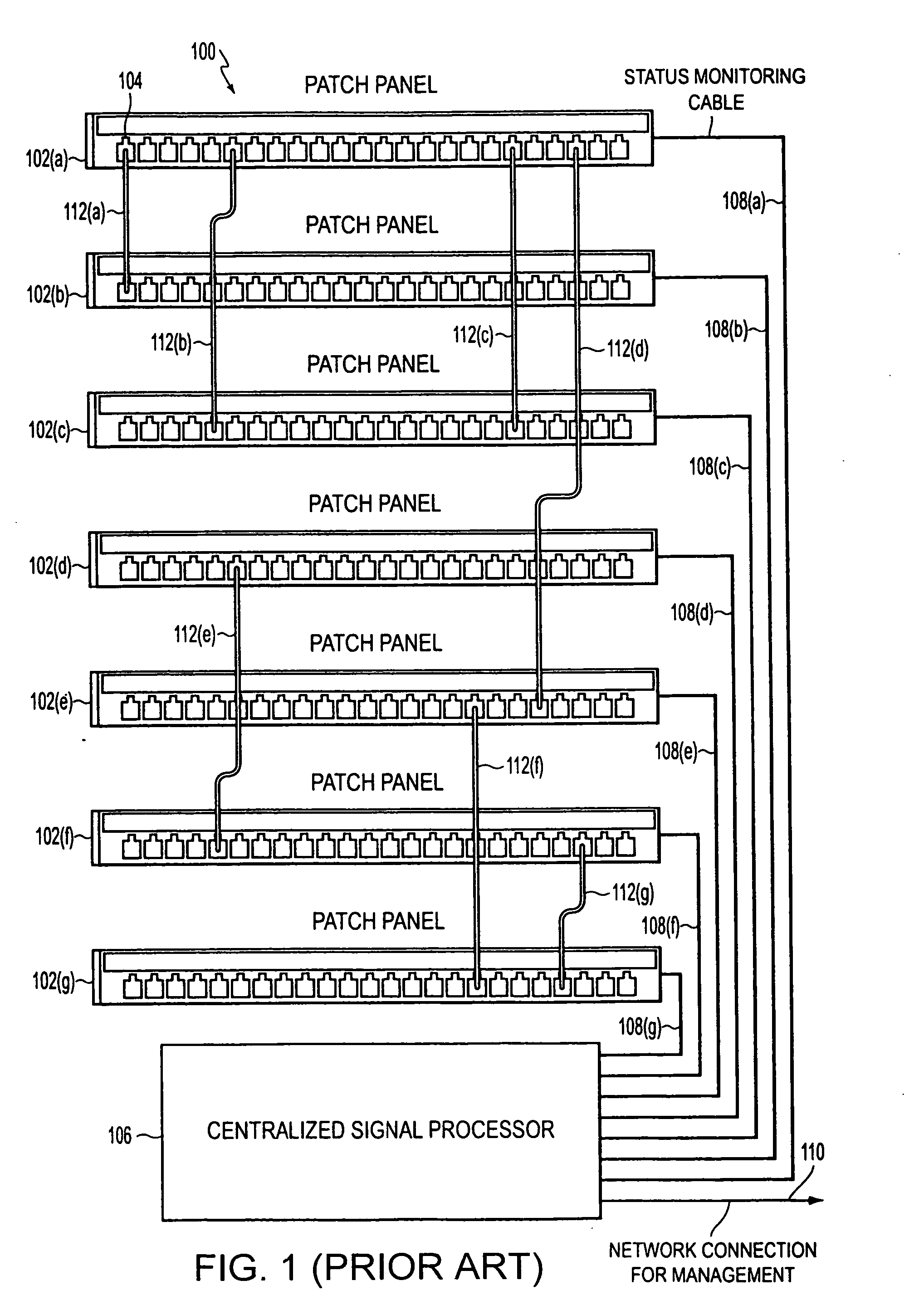
[0023]FIG. 1 presents an example of a prior art patch panel bank 100 in which individual patch panels 102(a-g) have been adapted to support the automated compilation of patch cord connectivity information. As shown in FIG. 1, each patch panel 102 has a plurality of patch panel ports 104 and is connected to a centralized signal processor 106 via a monitoring ribbon cable 108(a-g).

[0024]Patch cords 112(a-g) used to establish connectivity between two patch panel ports 104 may include a plurality of network conductors that support network data connections and additional out-of-band conductors that support out-of-band signal connections used by patch panel bank 100 to monitor the connectivity statu...


PUM


Abstract

A method and apparatus are provided for monitoring and reporting cable connectivity such as patch panel port-level connectivity on a real-time basis. For patch panel systems, the approach is based upon a distributed architecture that may be modularly scalable and may reduce, if not eliminate, the need for a centralized signal processor and complex cabling between patch panels and the centralized signal processor. Each patch panel may determine port level connectivity independently. Polling delays and polling-related overhead processing may be reduced or eliminated by supporting real-time monitoring of port connectivity at the port level. The approach provides improved real-time reporting of patch panel connectivity with reduced cabling complexity, increased reliability, and decreased maintenance costs. In addition, the approach is compatible with (i.e., may communicate with and be controlled by) a multipurpose network management system (NMS). In addition, a compatible revision system is provided.

Description

CROSS-REFERENCE TO RELATED APPLICATION[0001]This application claims the benefit of U.S. Provisional Application No. 60 / 624,753, filed Nov. 3, 2004 and entitled “Method and Apparatus for Patch Panel Patch Cord Documentation and Revision.”BACKGROUND OF THE INVENTION[0002]1. Field of Invention[0003]The present invention pertains to network cable management.[0004]2. Description of Related Art[0005]Communications networks are growing in number and complexity. Monitoring network connections, including the management of patch panel connections, is an important task in network management. There is a desire for a patch panel management architecture that is reliable and scalable.SUMMARY OF THE INVENTION[0006]A method and apparatus are provided for monitoring and reporting cable connectivity such as patch panel port-level connectivity on a real-time basis. For the patch panel systems example, the approach is based upon a distributed architecture that may be modularly scalable and may reduce, i...

Claims


Application Information

Patent Timeline
Patent Type & Authority Patents(United States)
IPC IPC(8): H01R3/00
CPCH01R13/641H04L41/0213H04Q1/136H04L43/0811H04L43/06
Inventor CAVENEY, JACK E.NORDIN, RONALD A.
Owner PANDUIT
Why Eureka
Try Eureka