
Relying party trust anchor based public key technology framework

a technology framework and trust anchor technology, applied in the field of digital security, can solve the problems of significant challenges, the pki model cannot effectively meet these requirements, and the relying party's use of the certificate revocation status validation field

Inactive Publication Date: 2006-12-14
IBM CORP
View PDF19 Cites 68 Cited by
  • Summary
  • Abstract
  • Description
  • Claims
  • Application Information

AI Technical Summary

Benefits of technology

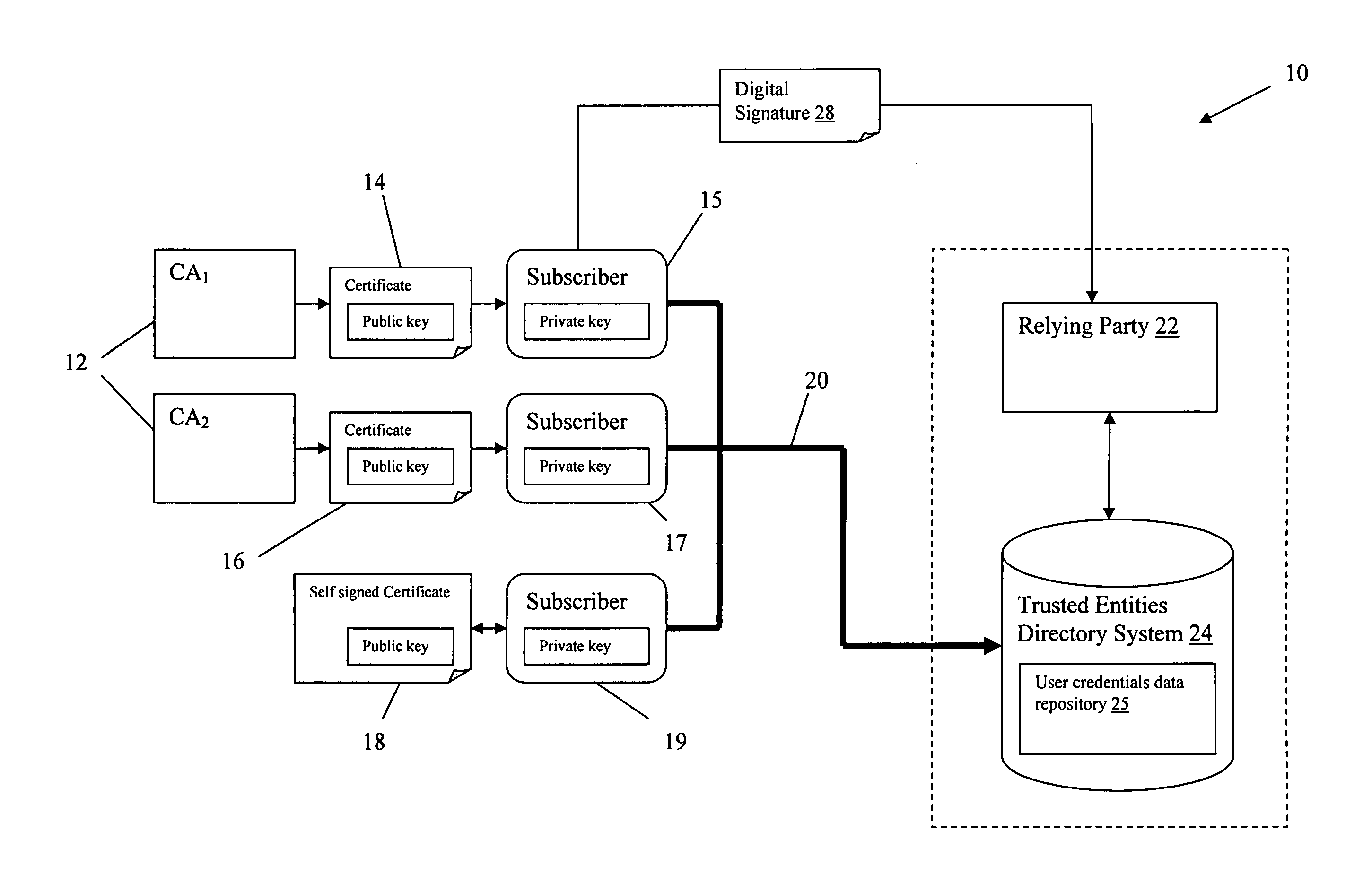
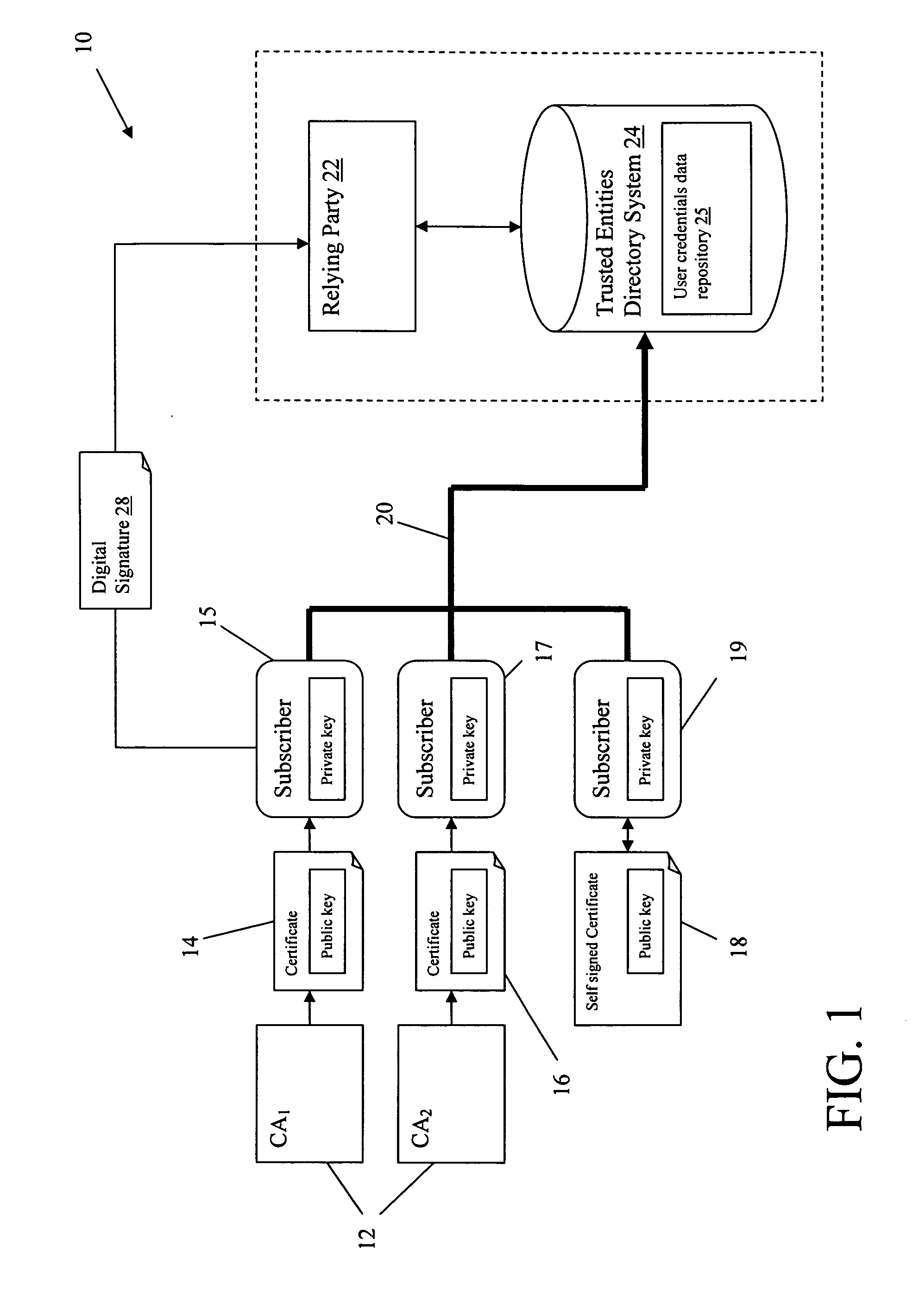
[0019] The present invention addresses the above-mentioned problems, as well as others, by providing a Public Key technology framework that is based on defining a trust anchor that is controlled by the relying party. In this model, the relying party securely binds a registered user to the corresponding user certificate. User certificates are stored in the user credentials repository controlled by the relying party. Subscribers in this framework are responsible for the security of their private keys and for obtaining certificates (similar to traditional PKI). A relying party, however, is responsible for verification of the subscriber's identity and for subscriber account lifecycle management (registering, suspending, deleting, updating, etc., certificates presented by users) in accordance with the relying party's user accounts provisioning policies, standards, regulations, and procedures.

Problems solved by technology

This can present significant challenges if many CAs exist, as well as if certificates are self-signed.
The traditional PKI model cannot effectively meet these requirements because: (1) issuing CAs are not considered to be trusted (in a sense of trust anchor) by a relying party, and they may not have any trust relationships defined between them; (2) self-signed and CA signed certificates cannot be easily accommodated in the same environment; and (3) since CAs are not trusted by the relying party, they cannot be used by the relying party for a certificate revocation status validation.
Thus, in the case of heterogeneous complex large scale PKI that encompasses self-signed certificates and independent CAs whose number can be unpredictable and vary over time, the traditional PKI model cannot provide a consistent level of trust and cannot use those CAs as well as self-signed certificates as trust anchors.

Method used


Image

  • Relying party trust anchor based public key technology framework
  • Relying party trust anchor based public key technology framework
  • Relying party trust anchor based public key technology framework

Examples


Embodiment Construction

Public Key Framework Overview

[0029] In a first embodiment of the present invention a framework is provided in which a relying party uses a Trusted Entities Directory (TED) associated with a user credentials data repository containing registered entities as a trust anchor. The user credentials data repository stores certificates for each user associated with the relying party. In this illustrative embodiment, a user, referred to as a subscriber, subscribes to a service provided by the relying party. In addition to storing certificates in the user credentials data repository, subscriber records may be maintained that include management information, such as a subscriber status, e.g., added, registered, deleted, etc.

[0030] To ensure security, the certificates are securely delivered to the user credentials data repository using a user registration process, which provides a binding step. The subscribers can be authenticated by relying applications using, for example, secure sockets lay...


PUM


Abstract

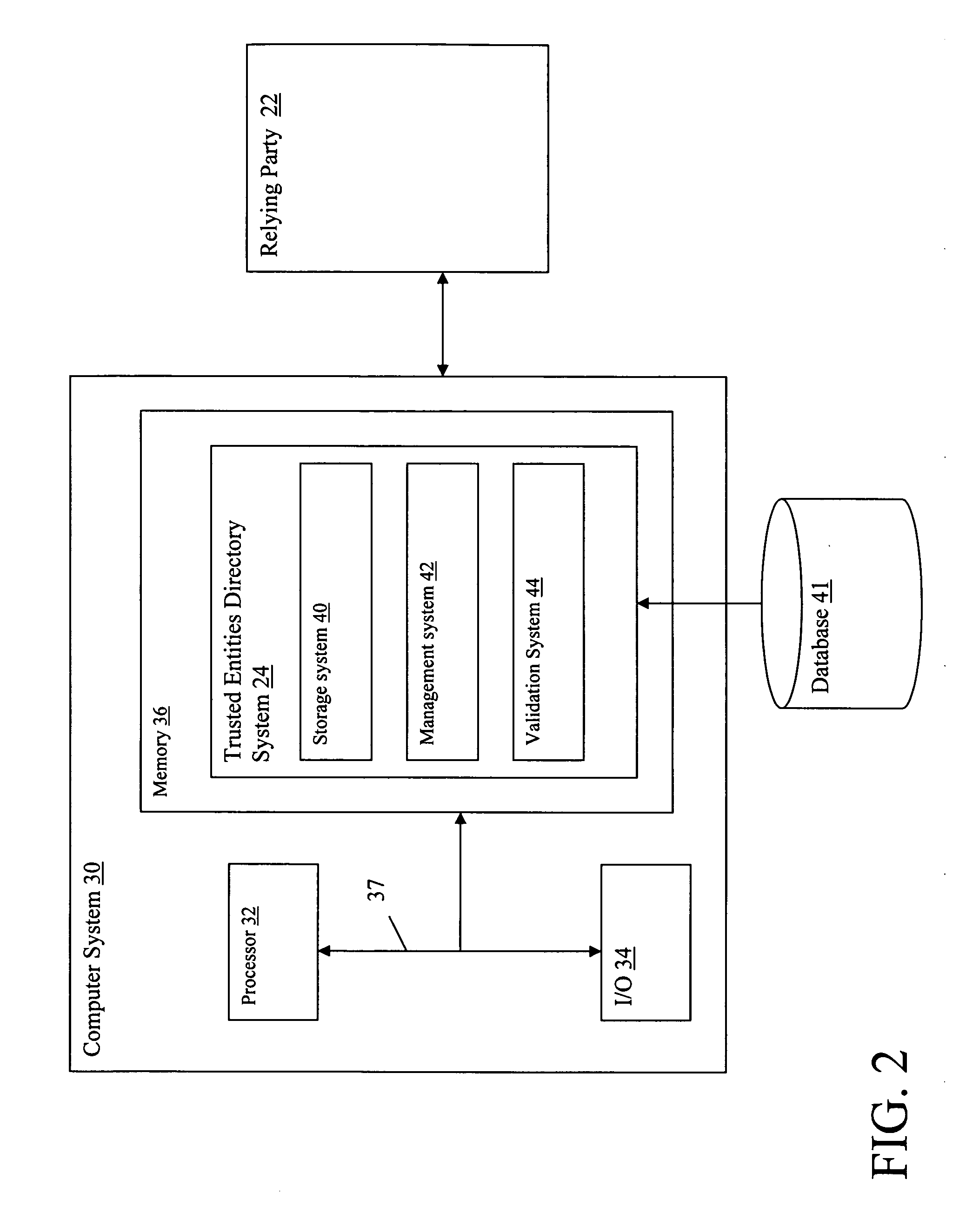
A public key (PK) framework for allowing a relying party to act as a trust anchor to authenticate a subscriber. The framework provides a directory system under the control of the relying party, wherein the directory system includes: a storage system for storing certificates received from subscribers in a database, wherein the certificates are issued by a plurality of different certificate authorities; a management system for managing records in the database associated with subscribers; and a validation system that allows the relying party to retrieve certificates from the database in order to authenticate subscribers.

Description

BACKGROUND OF THE INVENTION [0001] 1. Technical Field [0002] The present invention relates generally to digital security, and more specifically relates to a Public Key technology framework in which the relying party controls the trust anchor. [0003] 2. Related Art [0004] A PKI (public key infrastructure) enables users of a basically unsecure public network such as the Internet to securely and privately exchange data and execute transactions through the use of a public and a private cryptographic key pair, where the public keys are obtained and shared through a trusted Certificate Authority. Using the public key infrastructure users can be uniquely authenticated. A Certificate Authority uses a certificates data repository, usually an LDAP (Lightweight Directory Access Protocol) Directory for storing user certificates and information on revoked certificates. [0005] In the traditional PKI model, a two factor authentication scenario is commonly used in which the user uses: (1) a private...

Claims


Application Information

Patent Timeline
IPC IPC(8): H04L9/00
CPCH04L63/0823H04L2209/805H04L9/3268H04L9/006
Inventor KARCHOV, DAVID
Owner IBM CORP
Learn More