Axial flow sleeve for a turbine combustor and methods of introducing flow sleeve air

a technology of turbine combustor and flow sleeve, which is applied in the direction of hot gas positive displacement engine plants, combustion processes, lighting and heating apparatus, etc., can solve problems such as net energy loss, and achieve the effect of eliminating energy loss, precise control and metering of air

Inactive Publication Date: 2006-12-21
GENERAL ELECTRIC CO
View PDF8 Cites 38 Cited by
  • Summary
  • Abstract
  • Description
  • Claims
  • Application Information

AI Technical Summary

Benefits of technology

[0004] In accordance with a preferred aspect of the present invention, the flow sleeve is provided with an inlet which enables the air flowing into the inlet to change direction and enter the free flow stream of compressor discharge air between the liner and flow sleeve in a generally co-flow or coaxial direction, thus eliminating energy losses due to cross flow and accompanying momentum exchange. The inlet includes an annular plenum between the forward end of the flow sleeve and an annular casing about the inside of the flow sleeve. The flow sleeve is provided with a plurality of circumferentially spaced openings for injecting compressor discharge air into the plenum. The casing is provided with a plurality of circumferentially spaced apertures at its aft end for injecting the air from the plenum in a generally axial or co-flow direction with and into the free flow air stream. The inlet thus affords a precise control and metering of the air while simultaneously cooling the liner.

Problems solved by technology

This process causes a net loss in energy.

Method used


Image

  • Axial flow sleeve for a turbine combustor and methods of introducing flow sleeve air
  • Axial flow sleeve for a turbine combustor and methods of introducing flow sleeve air
  • Axial flow sleeve for a turbine combustor and methods of introducing flow sleeve air

Examples


Embodiment Construction

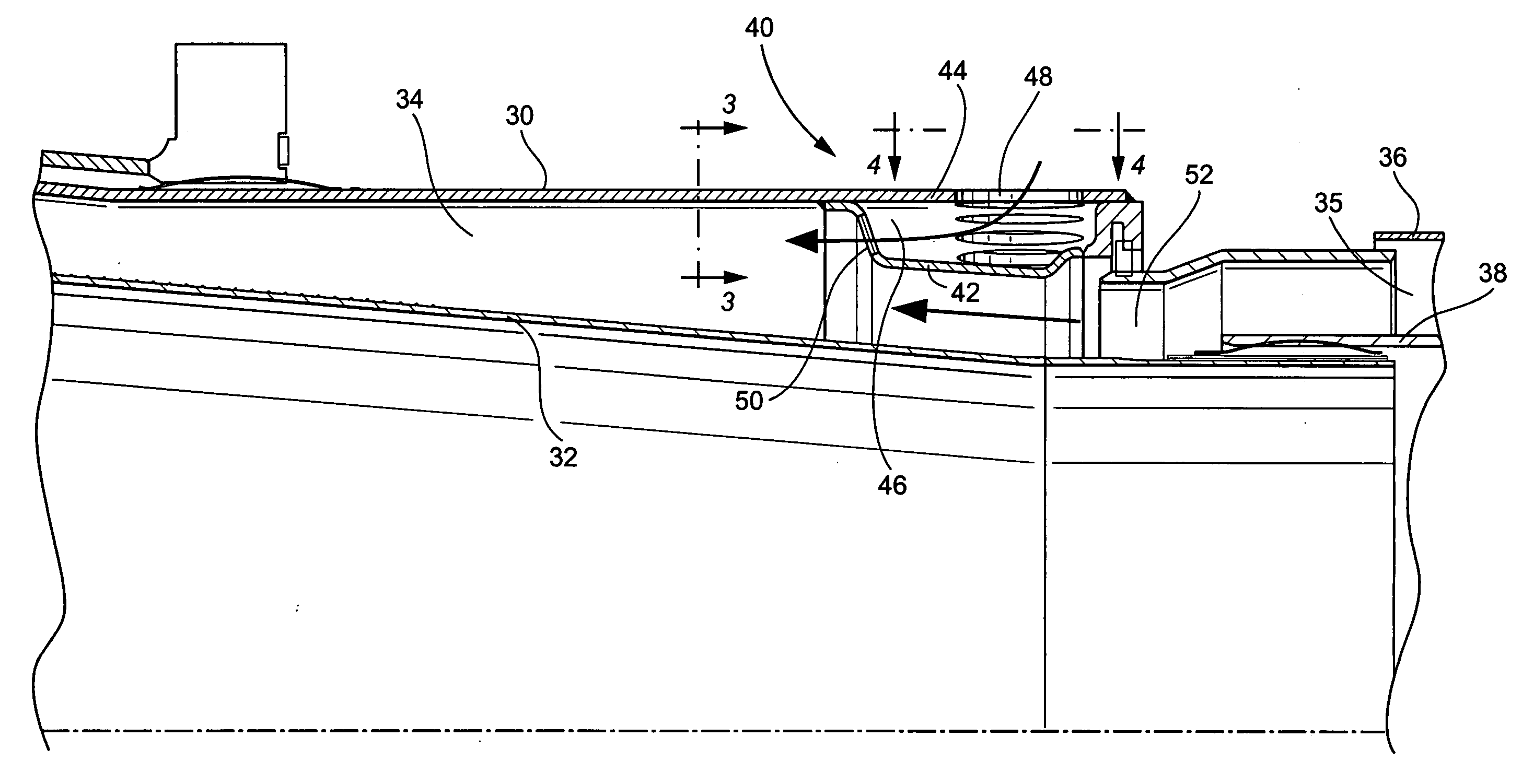
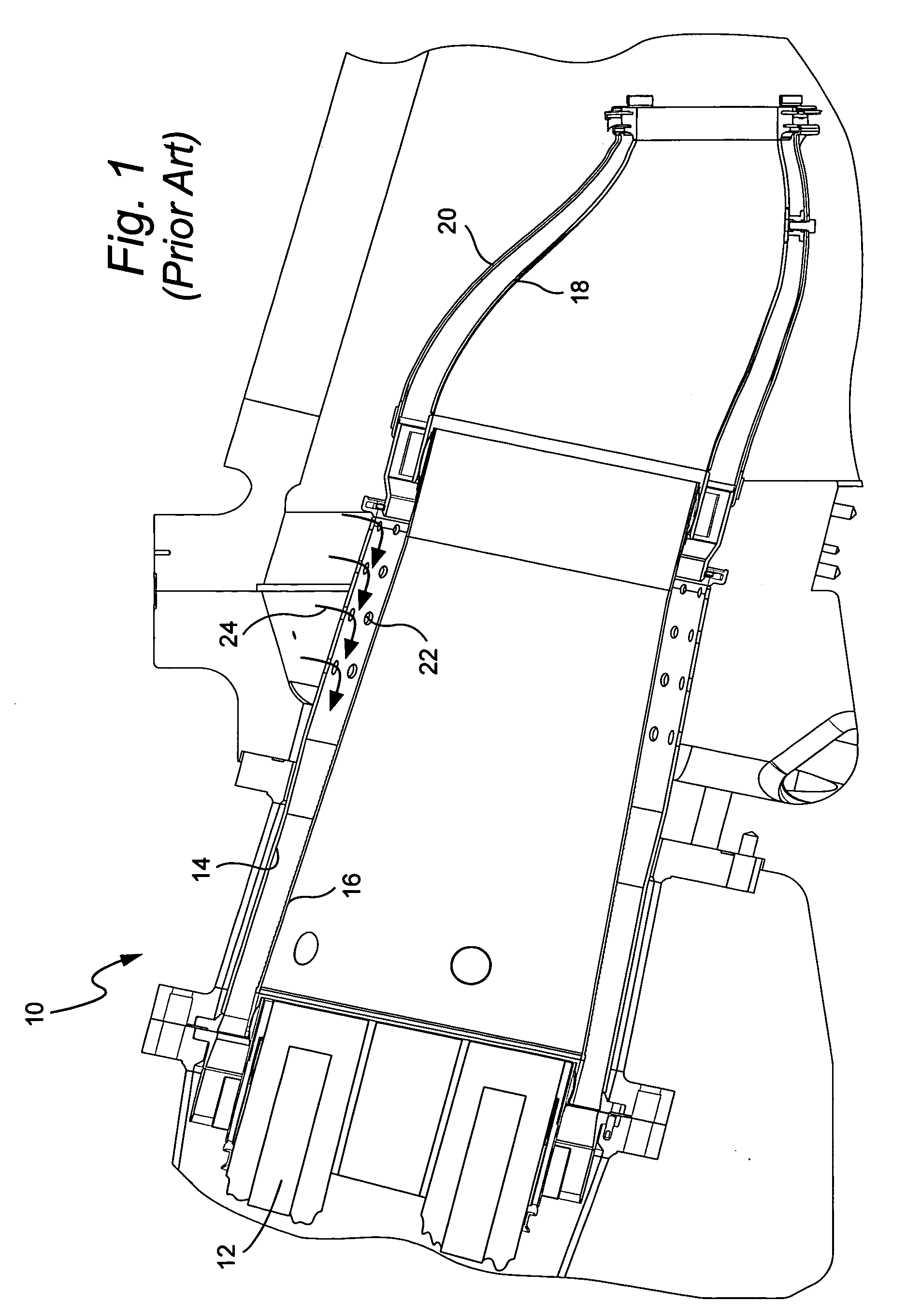
[0012] Referring now to the drawing figures, and particularly to FIG. 1, there is illustrated a combustor generally designated 10 according to the prior art. The combustor includes burners 12 at the aft end of the combustor, a flow sleeve 14 and liner 16 and a transition including a transition section piece body 18 and impingement sleeve 20. It will be appreciated that the area surrounding the flow sleeve 14 and the impingement sleeve 20 is supplied with compressor discharge air which in turn flows through openings (not shown) in the impingement sleeve and openings 22 in the flow sleeve for supplying compressor discharge air in a generally axial flow direction aft toward the burner end of the combustor. The supplied air mixes with the fuel in the burners 12, the fuel / air mixture combusts and flows forward within the liner 16. The energetic gases of combustion flow through the transition piece 18 toward the turbine section, not shown, of the gas turbine.

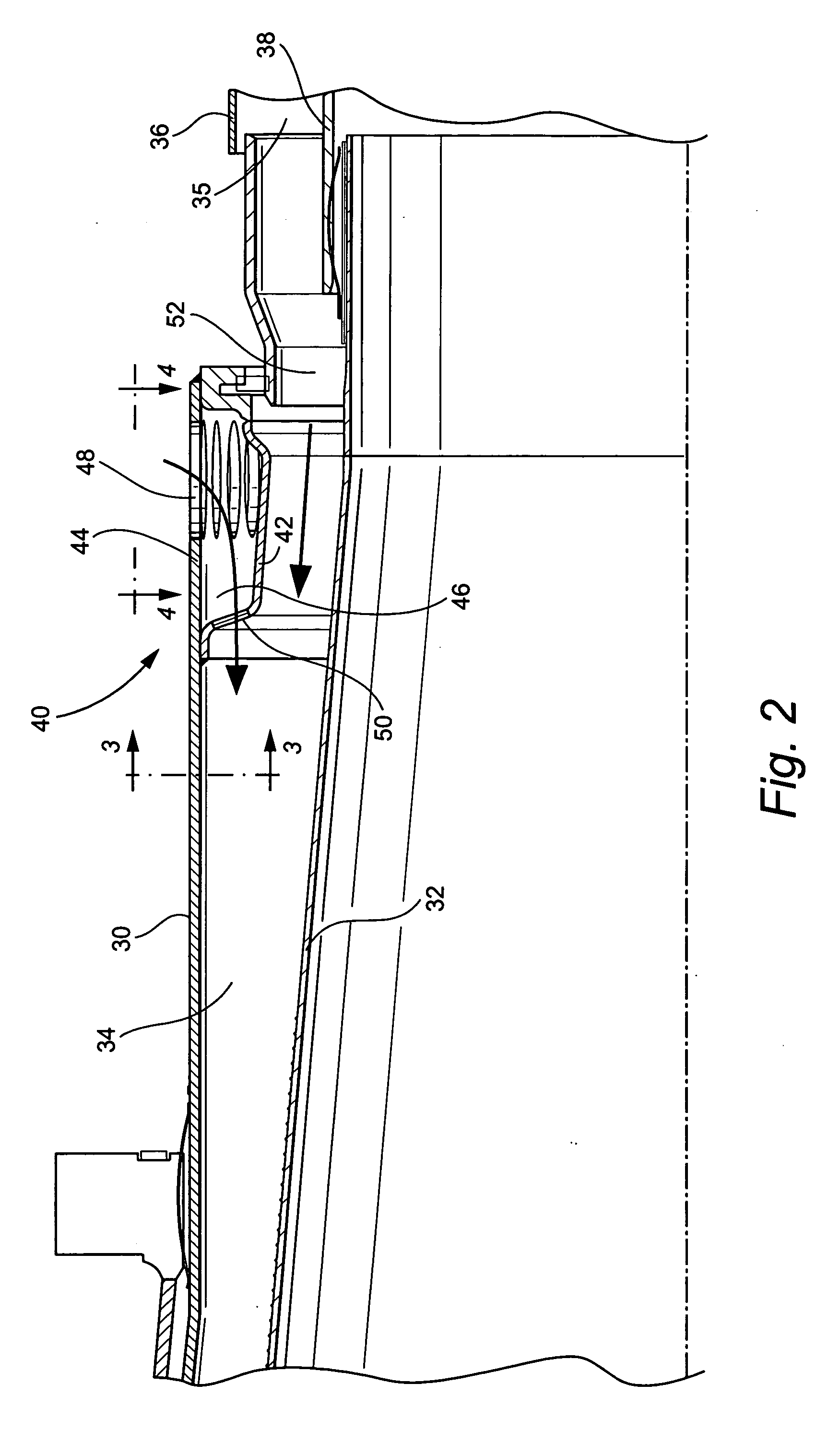
[0013] As illustrated in FIG....


PUM


Abstract

A combustor has a flow sleeve and a flow liner defining a generally axial flow direction of compressor discharge air toward combustor burners. A casing is secured to the forward end of the flow sleeve defining an annular plenum along the interior of the flow sleeve. Openings through the flow sleeve supply compressor discharge air into the plenum where the air changes direction for flow through apertures into and generally coaxially with the free air stream. The axial injection minimizes or eliminates energy losses due to cross flow injection within the axial air stream while continuing to cool the liner.

Description

BACKGROUND OF THE INVENTION [0001] The present invention relates to a gas turbine combustor having a flow sleeve and a liner for supplying compressor discharge air to combustor burners and particularly relates to a casing for turning compressor discharge air flowing radially through holes in the flow sleeve in an axial direction for flow in a generally parallel direction relative to the free stream air in the flow sleeve. The invention also relates to methods for turning the flow. [0002] In current combustors, a plurality of openings are provided about the flow sleeve for injecting air in a generally radial direction into the flow sleeve for impingement cooling the liner. The radially injected air is generally normal to the free stream air flowing within the flow sleeve. It will be appreciated that compressor discharge air flows through openings in the impingement sleeve of a transition piece and forms part of a free stream air flow in an aft direction and between the combustion flo...

Claims


Application Information

Patent Timeline
Patent Type & Authority Applications(United States)
IPC IPC(8): F23R3/02
CPCF23R3/04
Inventor LIPINSKI, JOHN JOSEPHJOHNSON, THOMAS EDWARDZIEGLER, ROBERT PAULSCHRODER, MARK STEWART
Owner GENERAL ELECTRIC CO
Why Eureka
Try Eureka