Thermoduct

a technology heat dissipation fins, which is applied in the direction of indirect heat exchangers, lighting and heating apparatus, etc., can solve the problems of inferior heat dissipation efficiency computer crashes or even stop operation, and heat dissipation problems of heat dissipation fins, etc., to achieve high heat dissipation efficiency, increase surface area, and inner wall

Inactive Publication Date: 2006-12-21
LEE TING WEI
View PDF13 Cites 41 Cited by
  • Summary
  • Abstract
  • Description
  • Claims
  • Application Information

AI Technical Summary

Benefits of technology

[0008] The primary objective of the present invention is to provide a thermoduct with high heat-dissipating efficiency.
[0009] To achieve the aforementioned objective, the thermoduct of the present invention comprises a tube, a metallic net and cupric powder, wherein the metallic net and cupric powder are disposed inside the metallic tube and function as a capillary texture. The inner wall of the tube has multiple trenches in order to increase the surface area of the inner wall and raise the capillarity for working fluid, which can promote the thermal conductivity and the permeability. The metallic net is inserted into the tube in order to promote the capillarity of the tube and to confine the cupric powder inside the gap between the metallic net and the inner wall of the tube, i.e. to confine the cupric powder inside the trenches. In comparison with the cupric rod used in the conventional technology, drawing out the metallic net is unnecessary in the present invention, so that in the present invention, the cupric powder can be free from being drawn out. The cupric powder adhering to the trenches can increase capillarity in the thermoduct. Further, the cupric powder and the metallic net will be sintered to adhere to the inner wall of the tube to provide working fluid with capillary texture, which is needed in the back flow of the working fluid.
[0010] In the present invention, the objective of dissipating heat is achieved via the cycling of absorbing / dissipating heat of the working fluid inside the thermoduct. The trenched tube incorporated with the capillary texture of the cupric powder and the metallic net enables the thermoduct of the present invention to have capillarity, permeability and thermal conductivity simultaneously, and thus, the backflow rate of the liquid working fluid is speeded up. The metallic net's taking the place of cupric rod enables the powder to firmly adhere to the trenches inside the tube, which can promote heat-dissipating effect.

Problems solved by technology

However, the heat-dissipating problems also arise with the promoted efficacy of the electronic products.
Exemplified by the computer, if the heat generated by the electronic elements cannot be drained, the temperature will rise, which induces the computer to crash or even stop operating.
However, the heat-dissipating efficiency of the aforementioned heat-dissipating fins is inferior, which results in that heat cannot be drained rapidly.
Further, the fabrication of the abovementioned thermoduct is uneasy, manpower-consuming, time-consuming, and expensive.

Method used


Image

  • Thermoduct
  • Thermoduct
  • Thermoduct

Examples


Embodiment Construction

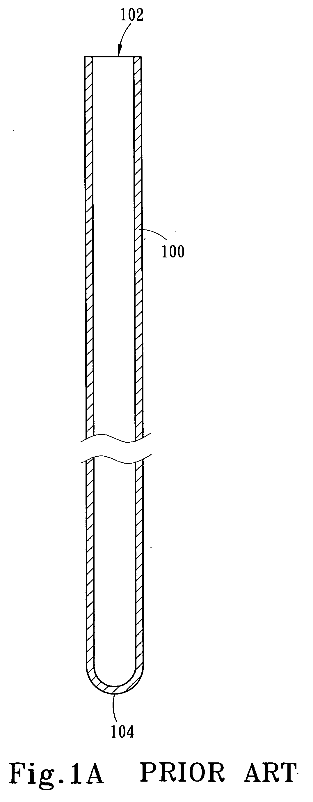
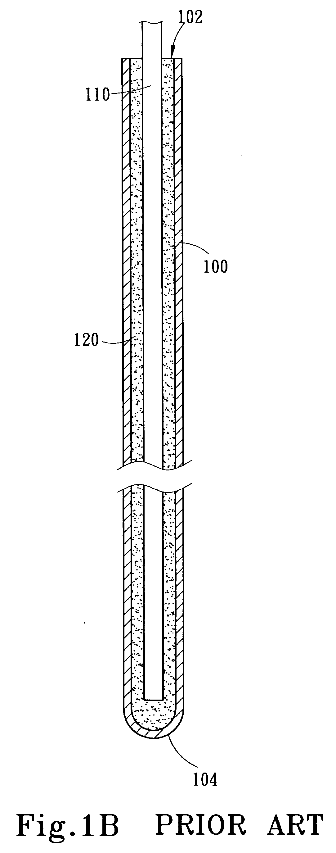
[0011]FIG. 1A˜FIG. 1C Prior Art illustrate schematically the fabrication method of a conventional thermoduct.

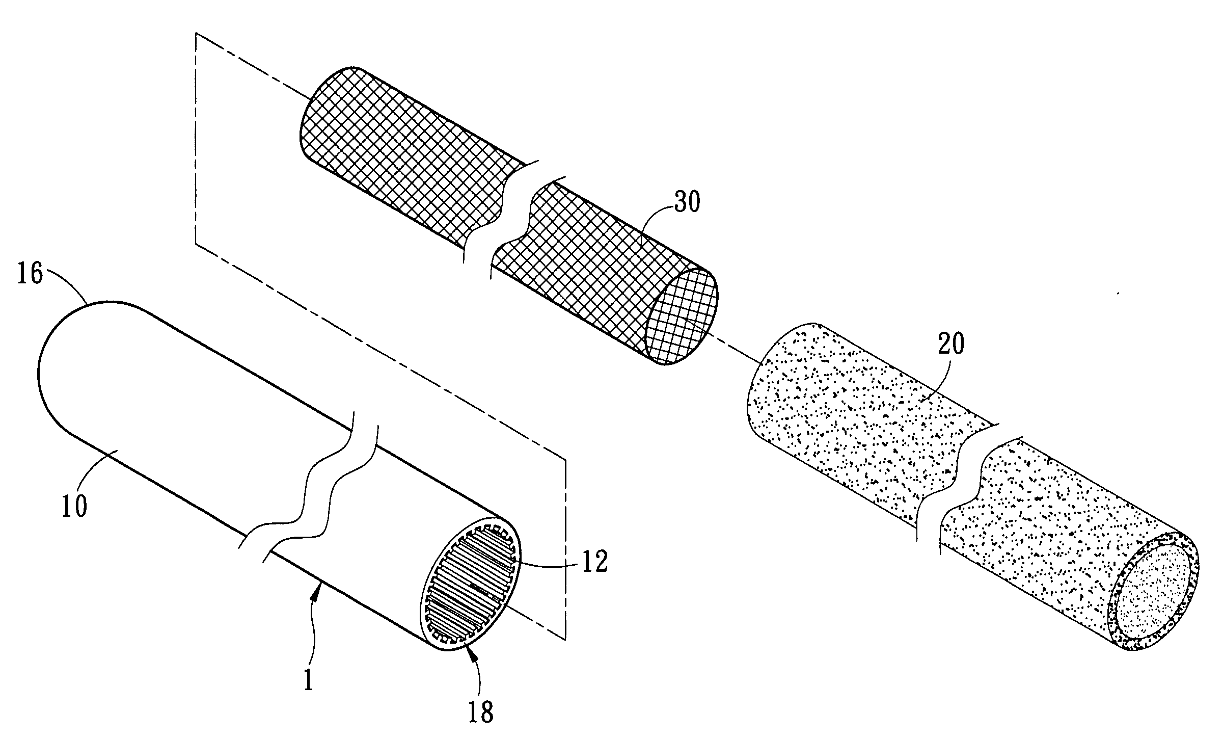
[0012]FIG. 2 illustrates schematically the structure of the thermoduct according to one embodiment of the present invention.

[0013]FIG. 3 shows schematically a sectional view of the thermoduct according to one embodiment of the present invention.

[0014]FIG. 4 shows schematically a practical application of the thermoduct according to one embodiment of the present invention.

DETAILED DESCRIPTION OF THE INVENTION

[0015] Refer to FIG. 2 disclosing a preferred embodiment of the thermoduct 1 of the present invention. The thermoduct 1 comprises a tube 10, cupric powder 20, and a metallic net 30, wherein the cupric powder 20 and the metallic net 30 are disposed inside the metallic tube 10 and function as a capillary texture.

[0016] Referring to FIG. 3, the tube 10 has an axial hollow portion 14, and the hollow portion 14 has an appropriate amount of working fluid (not shown in the dr...


PUM

PropertyMeasurementUnit
heataaaaaaaaaa
metallicaaaaaaaaaa
heat-dissipating efficiencyaaaaaaaaaa

Abstract

A thermoduct comprises a metallic tube with multiple trenches, cupric powder and a metallic net, wherein the metallic net and the cupric powder are disposed inside the metallic tube and function as a capillary texture. The cupric powder is sintered to adhere to recesses of trenches, and the metallic net is sintered to adhere to the inner wall of the metallic tube. In the present invention, the metallic net can confine the cupric powder inside the gap between the metallic net and the inner wall of the metallic tube, which enables the cupric powder to be sintered to firmly adhere to the recesses of the trenches; thus, the thermoduct can simultaneously have capillarity, permeability and thermal conductivity, and the backflow of the liquid working fluid is speeded up.

Description

FIELD OF THE INVENTION [0001] The present invention relates to a thermoduct, more particularly to a thermoduct having high heat-dissipating efficiency. BACKGROUND OF THE INVENTION [0002] With the rapid development of the 3C hi-tech industry, the 3C electronic products present advanced and novel designs persistently. However, the heat-dissipating problems also arise with the promoted efficacy of the electronic products. Therefore, most of the electronic products are equipped with heat-dissipating modules to drain the heat generated inside the electronic products. [0003] Exemplified by the computer, if the heat generated by the electronic elements cannot be drained, the temperature will rise, which induces the computer to crash or even stop operating. Therefore, a general PC always has heat-dissipating fins and electric fans. The heat-dissipating fins are made of multiple metallic plates and used to increase heat-dissipating area. In addition to increasing heat-dissipating area, an el...

Claims


Application Information

Patent Timeline
Patent Type & Authority Applications(United States)
IPC IPC(8): F28D15/00
CPCF28D15/046
Inventor HUANG, KUO-WEN
Owner LEE TING WEI
Why Eureka
Try Eureka