Supercharge Your Innovation With Domain-Expert AI Agents!

Tool retention apparatus and method

a tool and tool technology, applied in the direction of tool workpiece connection, manufacturing tools, portable drilling machines, etc., can solve the problems of unwanted torque being transferred from the tool to the tool assembly, pin and groove burring in use,

Active Publication Date: 2006-12-21
CATERPILLAR INC
View PDF37 Cites 1 Cited by
  • Summary
  • Abstract
  • Description
  • Claims
  • Application Information

AI Technical Summary

Benefits of technology

The present invention provides a tool assembly with a housing and a retention member that securely holds a work tool in place. The work tool can be easily installed and replaced without needing to disassemble the entire tool assembly. This design makes it easier and faster to change tools, which can save time and increase efficiency.

Problems solved by technology

The pin and groove are subject to burring in use, because of the repeated impact.
Moreover, the tool is restrained from rotation by the pin, so unwanted torque can be transferred from the tool to the tool assembly and the machine to which it is mounted.

Method used


Image

  • Tool retention apparatus and method
  • Tool retention apparatus and method
  • Tool retention apparatus and method

Examples


Embodiment Construction

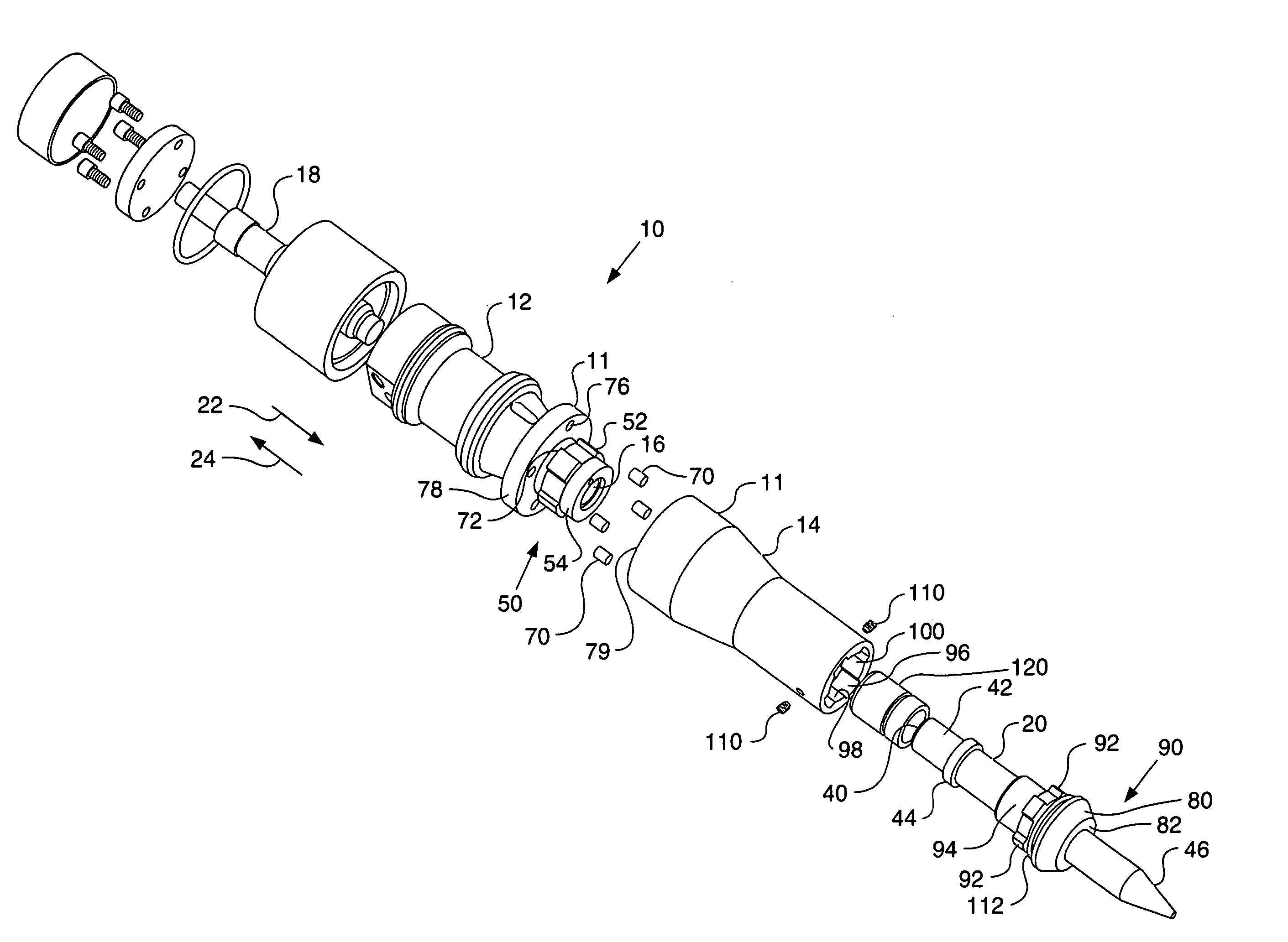
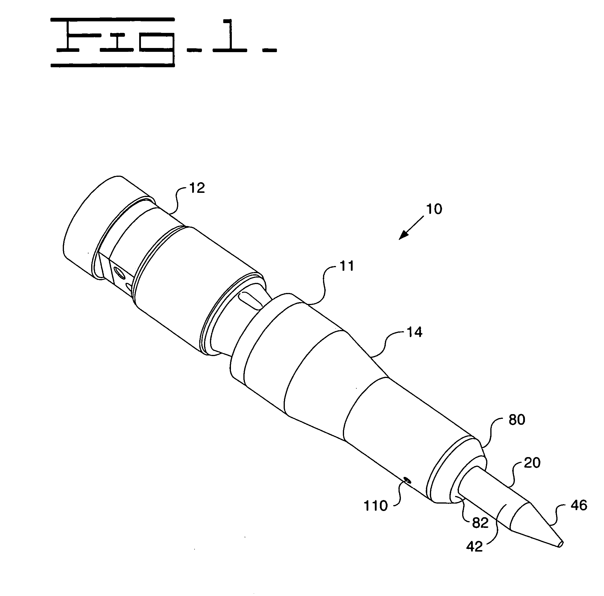
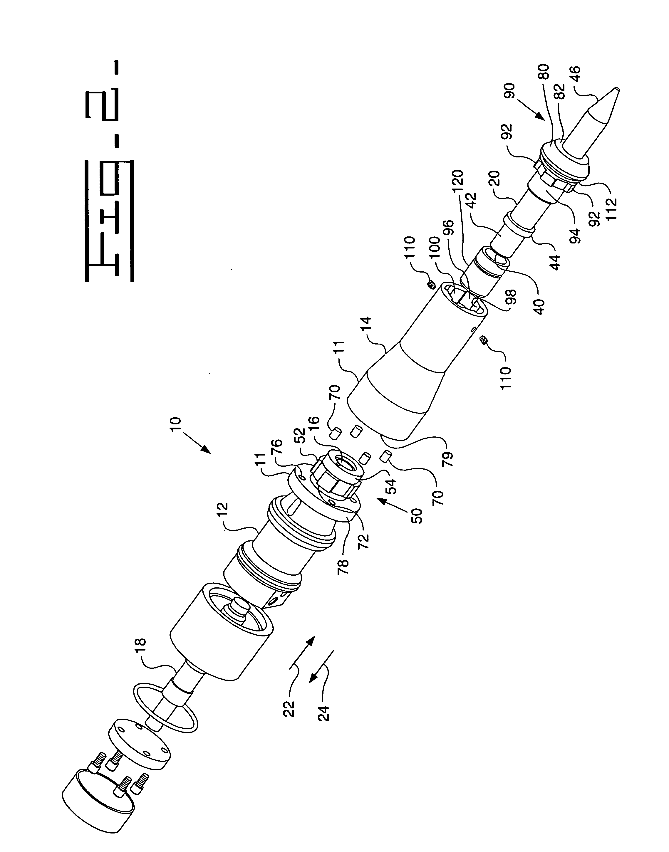
[0010] With reference to FIGS. 1 to 3 there is shown a tool assembly 10, specifically a hydraulic hammer assembly, which may be attached to a backhoe or excavator (not shown). The tool assembly 10 includes a housing 11, a chamber 16 defined in the housing 11, a piston 18 and a work tool 20. The housing 11 is a two part housing including an upper housing member 12 and a lower housing member 14, often referred to as a front head, which define an upper and lower chamber respectively, which together make up the chamber 16. The piston 18 is operatively housed in the chamber 16 such that the piston 18 can translate in the general direction of arrows 22 and 24. In particular, during a work stroke, the piston 18 moves in the general direction of arrow 22 so as to strike the work tool 20. Conversely, during a return stroke, the piston 18 moves in the general direction of arrow 24.

[0011] A hydraulic circuit (not shown) provides pressurized fluid to urge the piston 18 towards the work tool 20...


PUM

PropertyMeasurementUnit
sizeaaaaaaaaaa
pneumatic pressureaaaaaaaaaa
pressureaaaaaaaaaa

Abstract

A tool assembly (10), for example a hydraulic or pneumatic hammer assembly, includes a housing (11) defining a chamber (16), a removable reciprocating work tool (20) arranged in the chamber, and a tool retention member (80) having an aperture through which the work tool extends. The housing (11) includes an engaging structure (50) which permits the engagement of the tool retention member (80) with the housing by relative rotation of the tool retention member and housing. The work tool (20) is provided with retention structure (44) such as a retaining flange which prevents the removal of the work tool from the housing when the tool retention member is engaged with the housing. At least some of the disclosed embodiments may eliminate the need for a retainer pin, thereby allowing the work tool to rotate, possibly avoiding wear, increasing tool life and simplifying tool replacement.

Description

TECHNICAL FIELD [0001] The present disclosure relates generally to a tool assembly having a removable tool, and more specifically to a hydraulic or pneumatic hammer assembly having a removable work tool. BACKGROUND [0002] Hydraulic hammers are used on work sites to break up large hard objects before such objects can be moved away. Hydraulic hammers may be mounted to back hoes or excavators, or may be hand-held. Typically, the hammer assembly is powered by either a hydraulic or pneumatic pressure source. During a work or power stroke, high fluid pressure is applied to a first shoulder of a piston, thereby driving the piston in a forward direction. The piston then strikes a work tool, which is driven in the forward direction thereby causing a work tip of the work tool to strike the rock, concrete, asphalt or other hard object to be broken up. During a return stroke, fluid pressure is applied to a second shoulder of the piston in order to return the piston to its original position. [00...

Claims


Application Information

Patent Timeline
Patent Type & Authority Applications(United States)
IPC IPC(8): B23B45/16B25D11/00
CPCB23B2240/04B25D17/08Y10T279/17068Y10T279/17888B25D17/24
Inventor PILLERS, LAURITZ PHILLIP II
Owner CATERPILLAR INC
Features
  • R&D
  • Intellectual Property
  • Life Sciences
  • Materials
  • Tech Scout
  • Unparalleled Data Quality
  • Higher Quality Content
  • 60% Fewer Hallucinations
Learn More