
Motorcycle

Inactive Publication Date: 2006-12-21
HONDA MOTOR CO LTD
View PDF7 Cites 5 Cited by
  • Summary
  • Abstract
  • Description
  • Claims
  • Application Information

AI Technical Summary

Benefits of technology

[0009] It is an object of an embodiment of the present invention to provide a motorcycle that makes it possible to reduce the number of manufacturing steps of the rear swing-arm bracket.
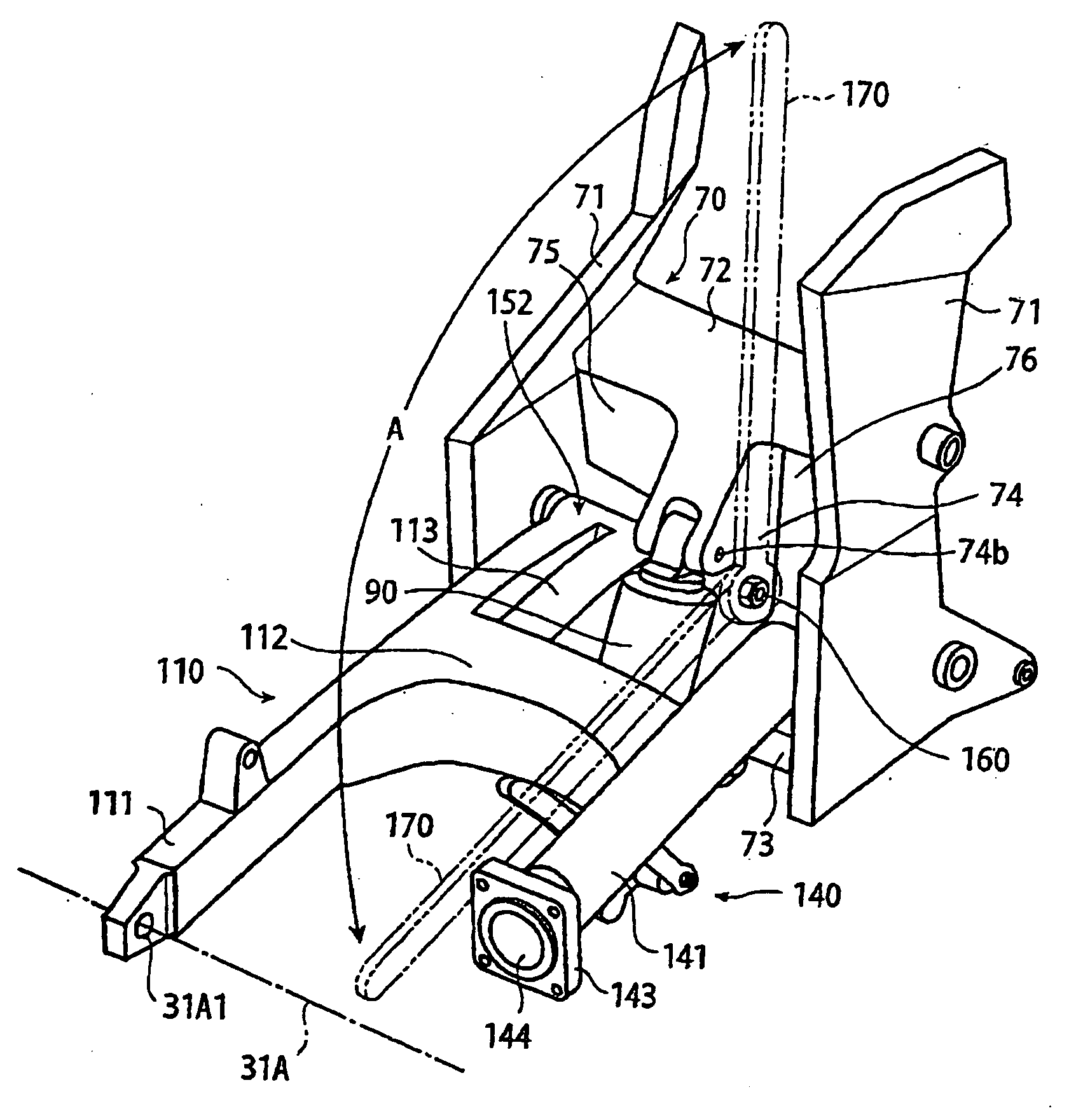
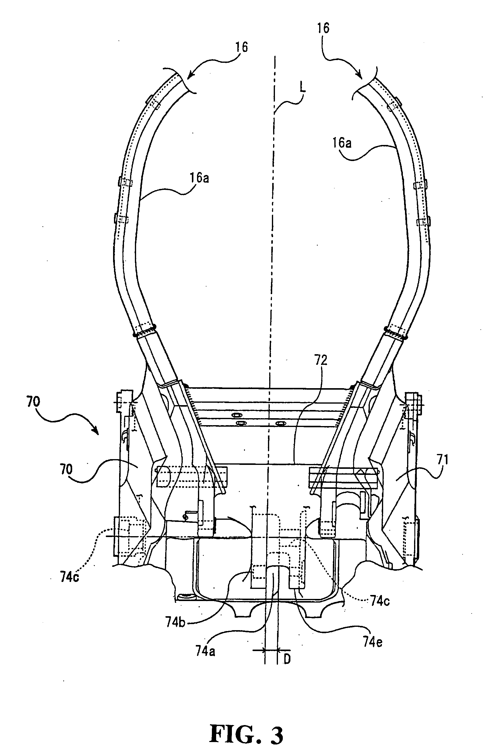
[0016] With the present invention, if a configuration is adopted in which the connection portion is provided with the concave portion, and in which the front end portion of the rear swing arm and the concave portion are disposed so that they partly overlap each other in the vehicle width direction, the position at which the connection portion to be provided can be set at a position biased toward the center with respect to the vehicle-body width direction to the utmost extent, while keeping the length of the pivot shaft of the rear swing arm long. Thus, it is possible to secure a sufficient space, into which the tool for fastening bolts, nuts and the like is inserted to perform the work, between an end of the pivot shaft pivotally supporting the rear swing arm and the shaft drive mechanism. Accordingly, it is possible to perform fastening work with the fastening tool inserted. As a result, it is possible to eliminate the step of cutting a thread in the frame member of the rear swing-arm bracket, into which thread the pivot shaft is screwed, so that it is made possible to reduce the number of manufacturing steps.

Problems solved by technology

Thus, the space used for inserting a fastening tool, such as a torque wrench or the like, for tightening a fastening, such as a nut or the like, on the pivot shaft is scarce.
For this reason, it has been difficult to insert a fastening tool into the space between the shaft drive mechanism and the connection portion to perform the work of tightening the pivot shaft via a fastening, such as a nut.
In this case, however, there is a problem wherein the number of steps required to manufacture the rear swing-arm bracket increases.

Method used


Image

  • Motorcycle
  • Motorcycle
  • Motorcycle

Examples


Embodiment Construction

[0028] A detailed description will be given below of an embodiment of the present invention with reference to the drawings.

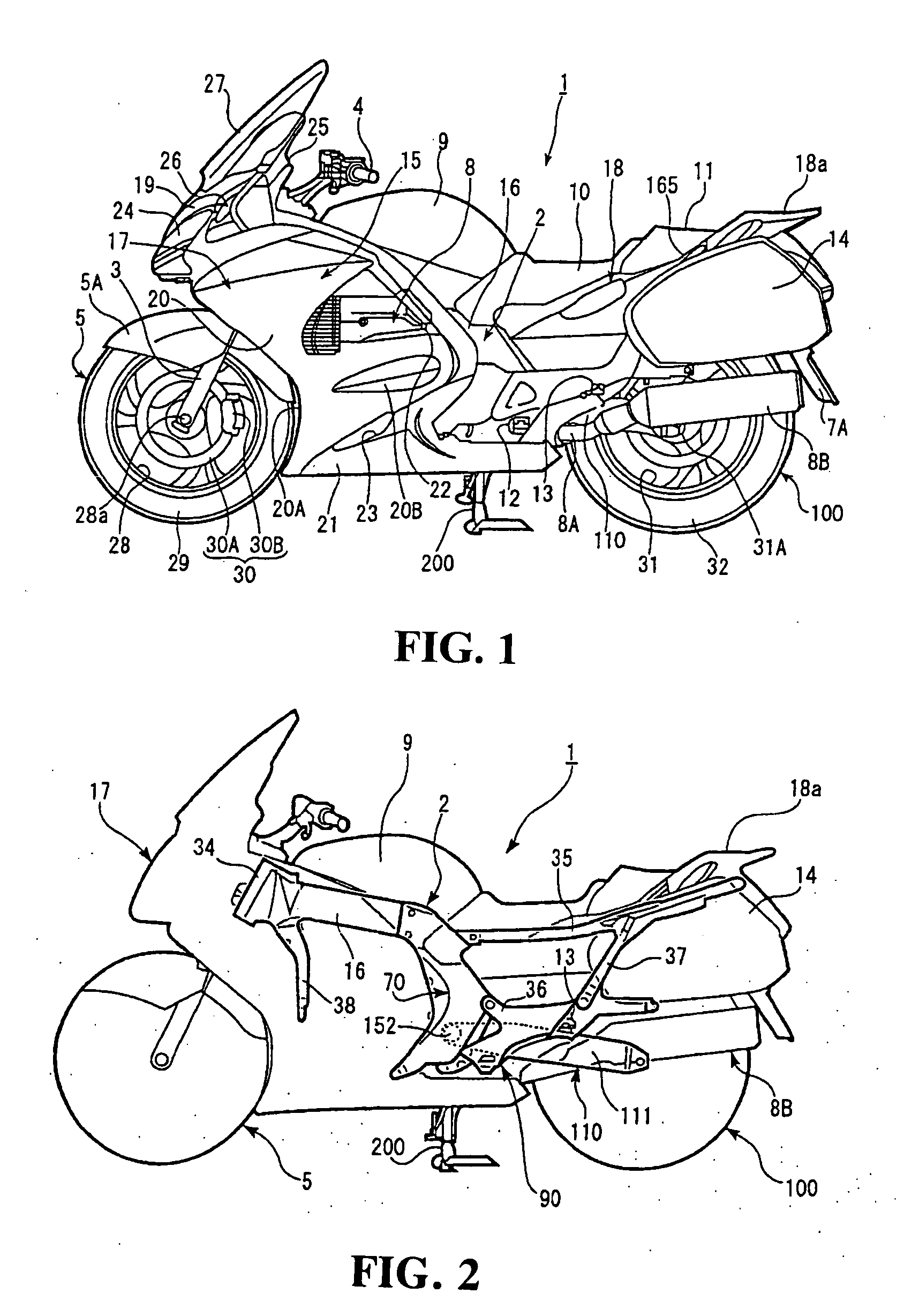
[0029]FIG. 1 is an overall schematic side view illustrating a motorcycle 1 provided with a rear swing-arm attachment structure of the embodiment according to the present invention. FIG. 2 is a side view of a frame of the motorcycle 1 viewed from a side. FIG. 1 illustrates a state in which the motorcycle 1 is supported by a stand 200. The description below will first provide an outline of the construction of the motorcycle.

[0030] As shown in FIG. 1, the motorcycle 1 includes a vehicle body frame 2, a left / right pair of front forks 3 pivotally supported by a front end portion of the vehicle body frame 2, a steering handlebar 4 attached to an upper end portion of the front forks 3, a front wheel 5 rotatably supported by the front forks 3, a rear swing arm (also referred to as “the swing arm”) 110 swingably supported by the vehicle body frame 2 with a rear wheel 7...


PUM


Abstract

A front end portion of a rear swing arm of a motorcycle is pivoted to a vehicle body frame via a rear swing-arm bracket. A rear wheel is rotatably supported by a rear end portion of the rear swing arm. The rear swing arm is provided with a shaft drive mechanism for driving the rear wheel. The rear swing-arm bracket includes a left / right pair of frame members, cross members and a connection portion. A front end portion of the shaft drive mechanism faces a right-side opening at a position biased towards the frame member. The connection portion is extendedly provided at a position biased toward the center line (the center) extending along the longitudinal direction of the vehicle. The front end portion of the rear swing arm is fastened to the frame member and the connection portion via a pivot shaft and a nut in a left-side opening.

Description

CROSS-REFERENCE TO RELATED APPLICATIONS [0001] The present application claims priority under 35 USC 119 to Japanese Patent Application No. 2005-176115 filed on Jun. 16, 2005 the entire contents of which are hereby incorporated by reference. FIELD OF THE INVENTION [0002] The present invention relates to a motorcycle in which a rear wheel is driven by a shaft drive mechanism. More specifically, to a motorcycle provided with a rear swing-arm bracket for pivotally supporting a front end portion of a rear swing arm via a pivot shaft, the rear swing arm rotatably supporting the rear wheel. DESCRIPTION OF BACKGROUND ART [0003] Motorcycles are known which operate by driving a rear wheel of the motorcycle via a shaft drive mechanism. Japanese Patent Laid-Open No. 2002-87364 discloses a motorcycle including a rear swing arm supporting a rear wheel. The rear swing arm is pivotally supported by left / right rear swing-arm brackets via the brackets and a pivot shaft, and is supported by a rear-whe...

Claims


Application Information

Patent Timeline
IPC IPC(8): B62M7/00B62K25/20B62M17/00
CPCB62K25/283
Inventor NAKANISHI, YUTAKA
Owner HONDA MOTOR CO LTD
Learn More