Gravitational separator and apparatus for separating floating particulate and volatile liquids from a stormwater stream adaptable for inline usage

a gravity separator and inline use technology, applied in the direction of centrifugal force sediment separation, sedimentation settling tanks, separation processes, etc., can solve the problems of untreated stormwater, unsatisfactory whole-sale diversion from the treatment system, and inability to meet the requirements of inline us

a gravity separator and inline use technology, applied in the direction of centrifugal force sediment separation, sedimentation settling tanks, separation processes, etc., can solve the problems of untreated stormwater, unsatisfactory whole-sale diversion from the treatment system, and inability to meet the requirements of inline us

US20060283814A1Inactive Publication Date: 2006-12-21AQUASHIELD

Image

  • Gravitational separator and apparatus for separating floating particulate and volatile liquids from a stormwater stream adaptable for inline usage
  • Gravitational separator and apparatus for separating floating particulate and volatile liquids from a stormwater stream adaptable for inline usage
  • Gravitational separator and apparatus for separating floating particulate and volatile liquids from a stormwater stream adaptable for inline usage

Examples


Embodiment Construction

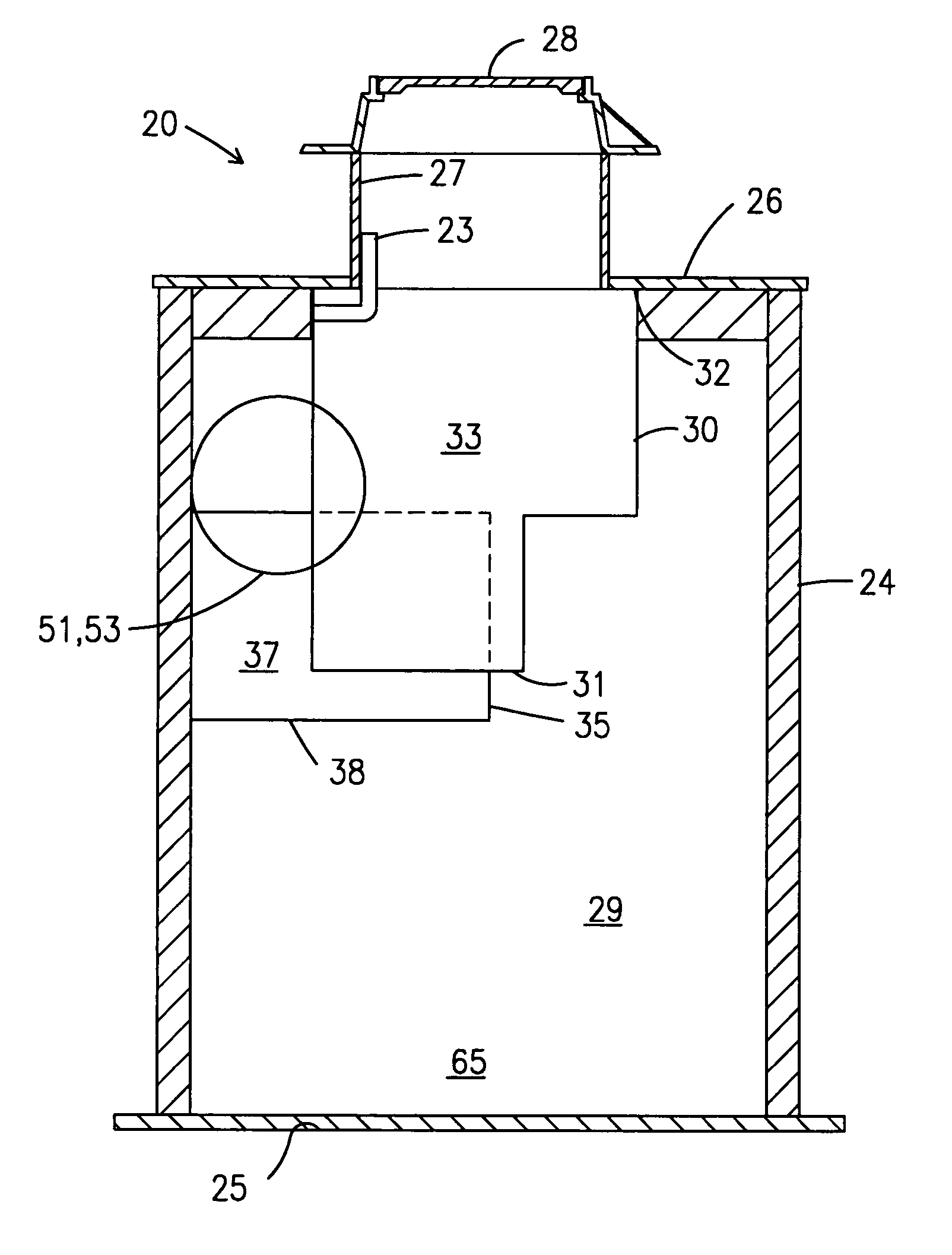
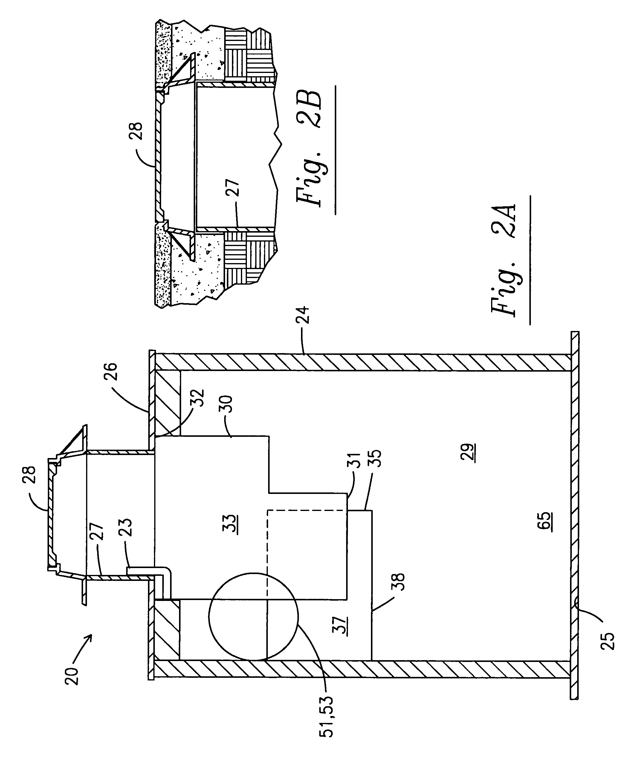
[0017] Turning first to FIG. 1, there is an illustrated embodiment of a hydrodynamic gravitational separator 20 according to the present invention. The depicted separator 20 is designed for use in the treatment of storm water where storm water is introduced to the separator 20 through inlet pipe 21 and treated storm water exits from the separator through outlet pipe 22. Because of the unique design of the separator an upstream weir to divert high flow condition water is not necessary. The interior chamber 29 of the separator 20 is defined by cylindrical inner wall 24, floor 25, and top 26. Preferably, the top 26 has a central opening to which is connected a riser 27 and the riser is fitted with a cover 28.

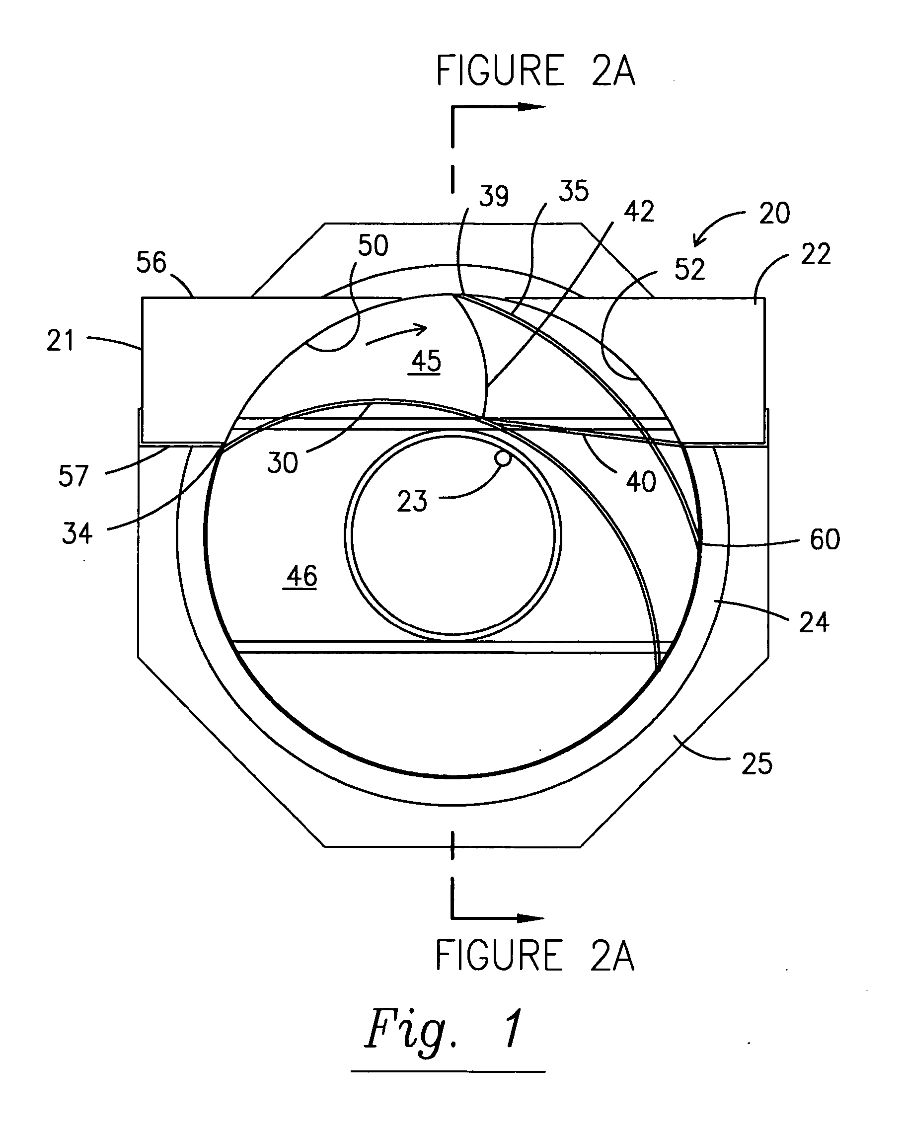
[0018] As most clearly shown in FIGS. 1 and 5, in operation, water from inlet pipe 21 enters chamber 29 through inlet 50 which is positioned between leading edges 34, 39 of interior baffle 30 and exterior baffle 35. Interior baffle 30 has an upper portion 61 fastened to top 26 of ...


PUM

PropertyMeasurementUnit
heightaaaaaaaaaa
heightaaaaaaaaaa
diameteraaaaaaaaaa

Abstract

A hydrodynamic gravitational separator has an input channel positioned to tangentially direct storm water into collection and treatment cavity while remaining operable in high flow conditions to divert excess storm water directly through to an outlet pipe.

Description

[0001] The present application claims priority to the Apr. 29, 2005 filing date of U.S. provisional patent application Ser. No. 60 / 676,111, which is incorporated herein.FIELD OF THE INVENTION [0002] The present invention relates generally to the treatment of storm water and provides for a gravitational system to remove non-floating particulate and a separator to isolate floating particles as well as liquids such as oil and gasoline residue which may be contained in storm water. BACKGROUND OF THE INVENTION [0003] It is known that residue from oil and gasoline spills at service stations, parking lots, and similar sites commonly remains at the site of the spill until washed away by water from rainfall or hose cleaning operation. The residue is often washed to a drain where it is likely to be carried to and mixed with the water supply from which drinkable water is ultimately taken. The protection of ground water and natural bodies of water requires systems for diverting or treating the ...

Claims


Application Information

Patent Timeline
21 Dec 2006
Publication
US20060283814A1
IPC
B01D21/26
CPC
B01D21/0027; B01D21/0042; B01D2221/12; B01D21/2411; B01D21/265; B01D21/02
Inventors
WILLIAMSON, J. KELLY; ROMINGER, ERIC