

Ion source
- Summary
- Abstract
- Description
- Claims
- Application Information
AI Technical Summary
Benefits of technology
Problems solved by technology
Method used
Image

Examples
Embodiment Construction
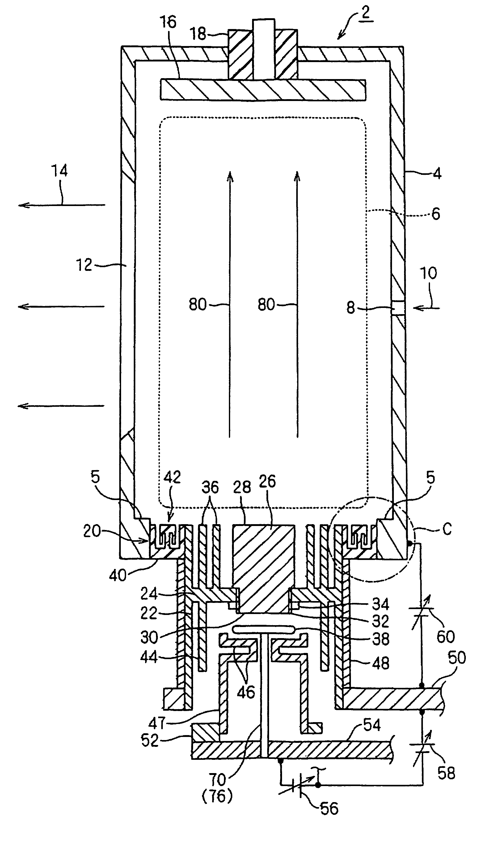
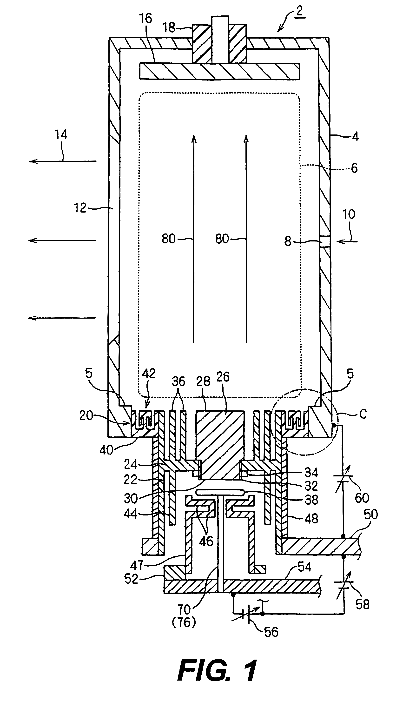
[0049]FIG. 1 is cross-sectional view of an exemplary, non-limiting embodiment of an ion source according to the invention. FIG. 2 is an enlarged view of Part C in FIG. 1.
[0050] An ion source 2 has a structure to heat a cathode 26 by a filament 38 and emit thermal electrons from the cathode 2 into a plasma generating chamber also serving as an anode. The ion source 2 is sometimes called an indirectly heated cathode type ion source.
[0051] The plasma generating chamber 4 is for example of a rectangular parallelepiped. Into the plasma generating chamber 4 is introduced a desired gas (including in the state of vapor) 10 for generating plasma 6 via a gas inlet 8. The gas 10 includes desired elements (for example dopant of B, P, As). To be more specific, the gas may include a material gas such as BF3, PH3, A3H3 and B2H6.
[0052] In one wall surface of the plasma generating chamber 4 (on one of the long side walls) is provided an ion extraction port 12 for extracting ion beams 14. The ion ...
PUM
 Abstract
Description
Claims
Application Information