
Off-axis projection optical system and extreme ultraviolet lithography apparatus using the same

a technology which is applied in the field of optical system and lithography apparatus using the same, can solve the problems of stray light blocking shielding member b>4/b>′, difficult and/or impossible to use refractive optical device for euv light, etc., and achieve the effect of reducing third order aberration

Active Publication Date: 2006-12-21
SAMSUNG ELECTRONICS CO LTD
View PDF1 Cites 50 Cited by
  • Summary
  • Abstract
  • Description
  • Claims
  • Application Information

AI Technical Summary

Benefits of technology

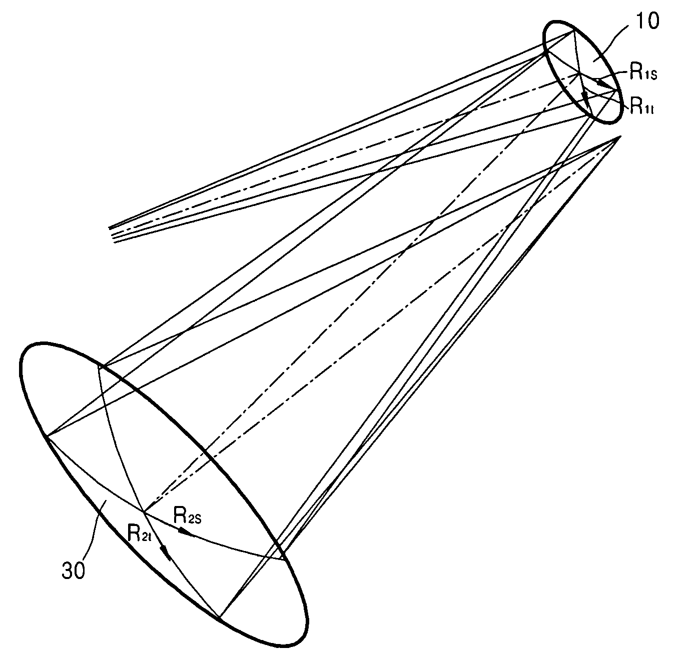
[0024] An example embodiment of the present invention provides an off-axis projection optical system. The off-axis projection optical system may include a first mirror for reflecting a EUV beam and a second mirror for reflecting the EUV beam. The first and the second mirrors may be arranged off-axially and configured to reduce third order aberration.
[0025] An example embodiment of the present invention provides a lit...

Problems solved by technology

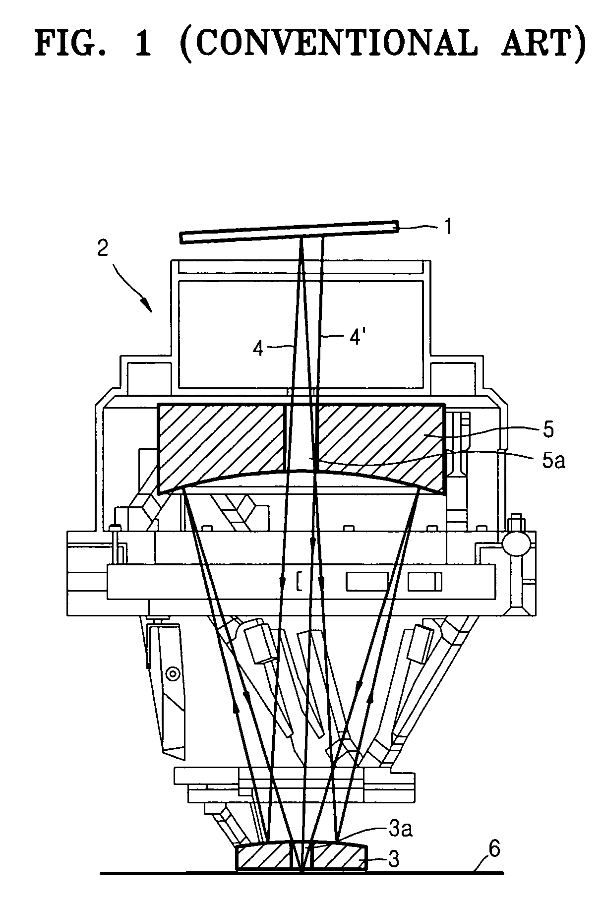
Because most materials absorb light in the EUV band, it may be difficult and / or impossible to use a refractive optical device for EUV light.
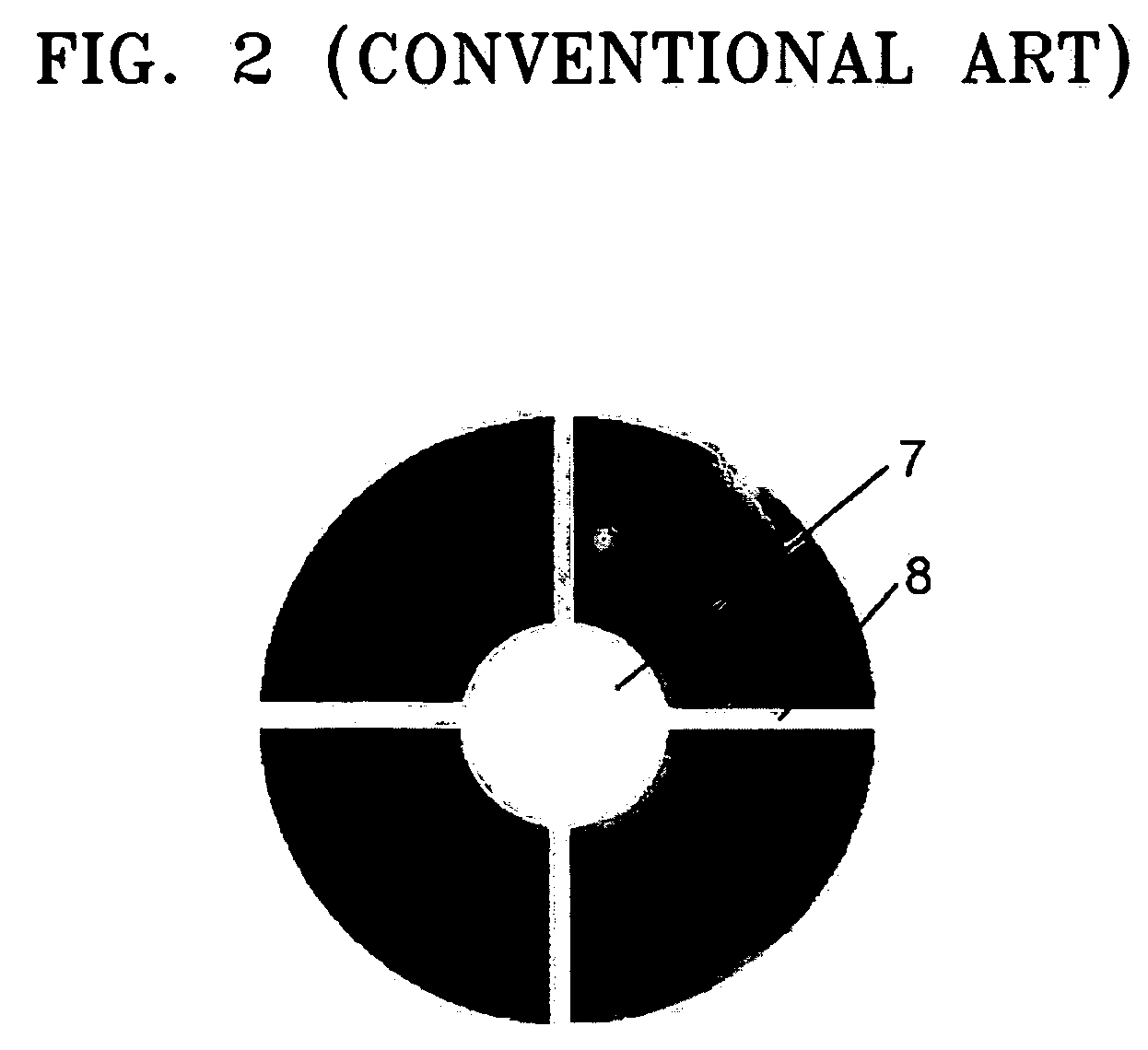
A drawback of conventional on-axis projection optical systems is that the shielding member 7 for blocking the stray light 4′ is necessary.

Method used


Image

  • Off-axis projection optical system and extreme ultraviolet lithography apparatus using the same
  • Off-axis projection optical system and extreme ultraviolet lithography apparatus using the same
  • Off-axis projection optical system and extreme ultraviolet lithography apparatus using the same

Examples


Embodiment Construction

[0033] Detailed illustrative embodiments of the present invention are disclosed herein. However, specific structural and functional details disclosed herein are merely representative for purposes of describing example embodiments of the present invention. This invention may, however, be embodied in many alternate forms and should not be construed as limited to only the embodiments set forth herein.

[0034] It should be understood that, although the terms first, second, etc. may be used herein to describe various elements, these elements should not be limited by these terms. These terms are only used to distinguish one element from another. For example, a first element could be termed a second element, and, similarly, a second element could be termed a first element, without departing from the scope of the present invention. As used herein, the term “and / or” includes any and all combinations of one or more of the associated listed items.

[0035] The terminology used herein is for the p...


PUM


Abstract

An off-axis projection optical system including first and second mirrors that are off-axially arranged is provided. The tangential and sagittal radii of curvature of the first mirror may be R1t and R1s, respectively. The tangential and sagittal radii of curvature of the second mirror may be R2t and R2s, respectively. The incident angle of the beam from an object point to the first mirror 10 may be i1, and an incident angle of the beam reflected from the first mirror 10 to the second mirror 30 is i2. The values of R1t, R1s, R2t, R2s, i1 and i2 may satisfy the following Equation. R1t cos i1=R2t cos i2 R1s=R1t cos2i1 R2s=R2t cos2i2

Description

PRIORITY STATEMENT [0001] This application claims the benefit of priority to Korean Patent Application No. 10-2005-0052727, filed on Jun. 18, 2005, in the Korean Intellectual Property Office, the entire contents of which is incorporated herein by reference. BACKGROUND OF THE INVENTION [0002] 1. Field of the Invention [0003] Example embodiments of the present invention relate to an off-axis projection optical system and an extreme ultraviolet (EUV) lithography apparatus using the same. [0004] 2. Description of the Related Art [0005] In a photolithography process of a semiconductor manufacturing process, a light exposure technology used to realize a direct writing resolution of less than 100 nm may involve the use of a light exposure wavelength within the EUV band. In EUV lithography technology, extreme ultraviolet light having a very short wavelength of less than 100 nm, for example, a wavelength of about 13.5 nm, may be used. [0006] Because most materials absorb light in the EUV ban...

Claims


Application Information

Patent Timeline
IPC IPC(8): G21G5/00A61N5/00
CPCG03F7/70941G03F7/70241G03F7/70091
Inventor CHANG, SEUNG-HYUKSONG, I-HUNPARK, YOUNG-SOOKIM, SUK-PILKIM, HOON
Owner SAMSUNG ELECTRONICS CO LTD
Learn More