Microphone and a method of manufacturing a microphone

a manufacturing method and microphone technology, applied in the direction of generators/motors, electrostatic generators/motors, electrical transducers, etc., can solve the problems of reducing the durability of the microphone, affecting the performance of the microphone, and affecting the quality of the microphone. , to achieve the effect of reducing the siz

Inactive Publication Date: 2006-12-21
TOKYO UNIV OF THE +1
View PDF10 Cites 38 Cited by
  • Summary
  • Abstract
  • Description
  • Claims
  • Application Information

AI Technical Summary

Benefits of technology

[0009] According to the technology in the above publication, the direction of the sound source can be identified with one diaphragm. A microphone that can identify the direction of the sound source can be reduced in size.

Problems solved by technology

Therefore, when the diaphragm vibrates for a long period of time, the diaphragm may deform from its initial shape due to fatigue.
In this case, the identification of the direction of the sound source may become inaccurate.
In other words, with the conventional technology, the microphone identifying the direction of the sound source by only one diaphragm may not have high durability.
In order to increase durability, if the strength of the diaphragm is increased in the thickness direction thereof, it will become more difficult to vibrate.
However, it will no longer be possible to identify the direction of the sound source if vibration of the diaphragm is simply inhibited.

Method used


Image

  • Microphone and a method of manufacturing a microphone
  • Microphone and a method of manufacturing a microphone
  • Microphone and a method of manufacturing a microphone

Examples


embodiment 1

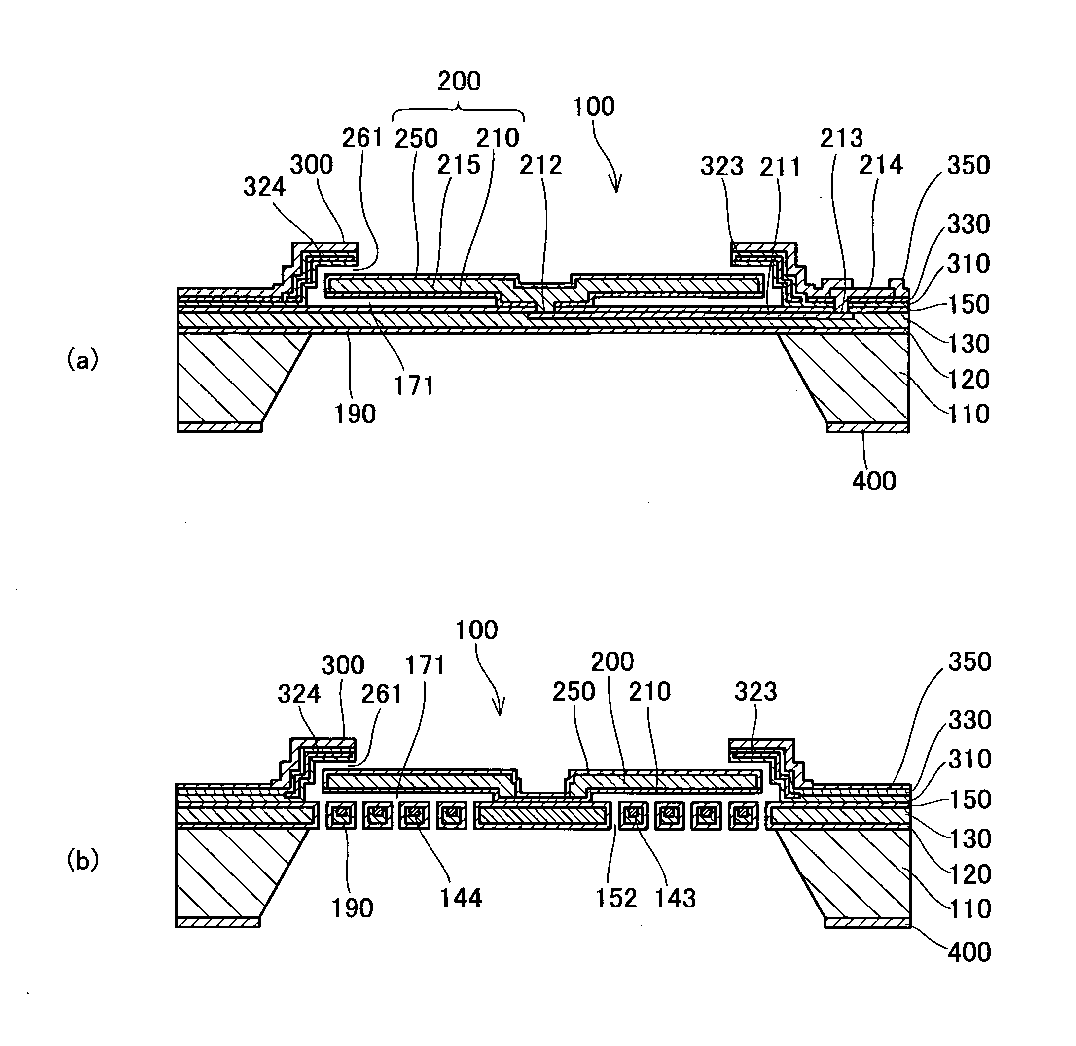
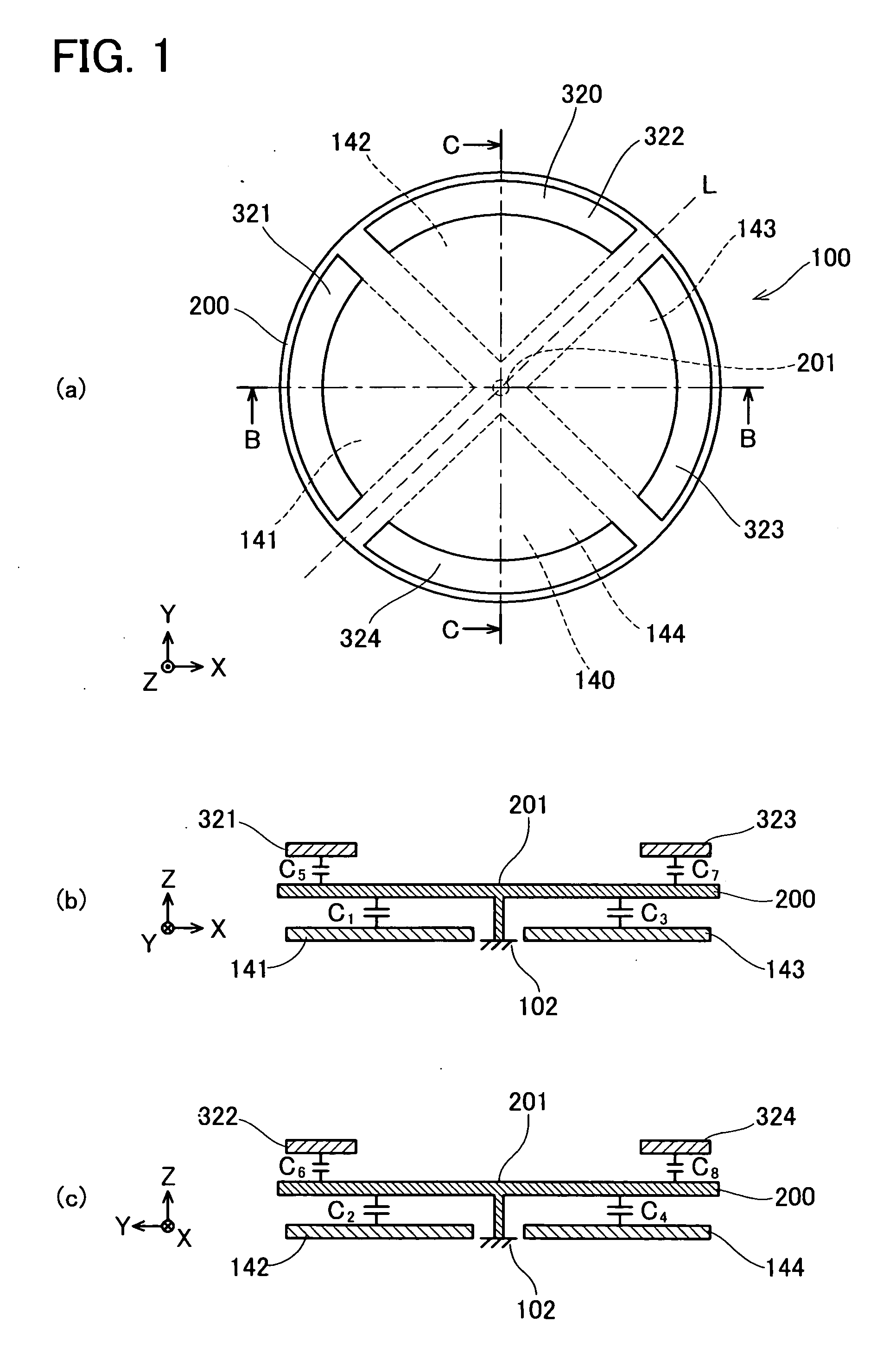
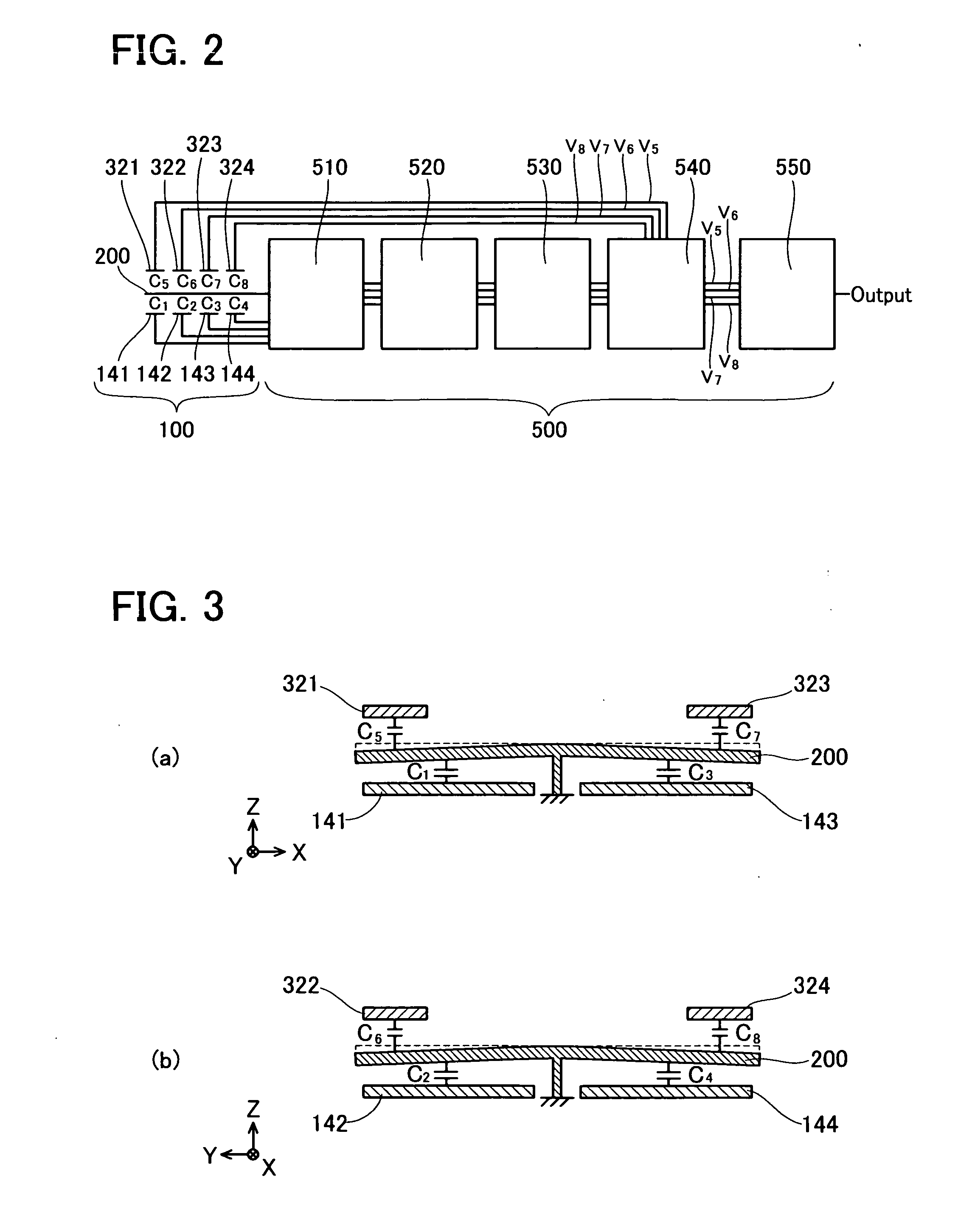
[0128]FIG. 1 depicts the general concept of a microphone 100 as the first embodiment. FIG. 1(a) is a plan view of the microphone 100. FIG. 1(b) is a vertical cross-section view corresponding to line B-B shown in FIG. 1(a). FIG. 1(c) is a vertical cross-section view corresponding to line C-C shown in FIG. 1(a).

[0129] The microphone 100 comprises a circular diaphragm 200. The diaphragm 200 is supported to the frame 102 of the microphone 100 at a center portion 201 of the diaphragm 200.

[0130] Four upper electrodes 321, 322, 323, 324 are arranged to a member (not shown) that is fixed to the frame 102. The four upper electrodes 321, 322, 323, 324 are positioned facing the front surface of the diaphragm 200 (the surface that receives acoustic waves). The four upper electrodes 321, 322, 323, 324 will be collectively referred to as upper electrodes 320. The upper electrodes 320 are arranged at equal intervals in the circumferential direction of the circular diaphragm 200. Each of the uppe...

embodiment 2

[0170] Next, the second embodiment of the present invention will be described in detail below with reference to the drawings. FIG. 6 shows the microphone 100b in this embodiment. In this embodiment, capacitors serving as sensors and capacitors serving as actuators are arranged on the same surface of the diaphragm (the front surface which receives acoustic waves).

[0171]FIG. 6(a) is a plan view of a microphone 100b. FIG. 6(b) is a vertical cross-section view corresponding to line D-D of FIG. 6(a).

[0172] Microphone 100b comprises a circular diaphragm 200 that is identical to the first embodiment. The diaphragm 200 is supported by the frame 102 of the microphone 100b at a center portion 201 of the diaphragm 200.

[0173] Four second electrodes 141f, 142f, 143f, 144f are arranged facing the front surface of the diaphragm 200. The four second electrodes 141f, 142f, 143f, 144f may be collectively referred to as the second electrodes 140f. Each of the second electrodes 140f is formed in an ...

embodiment 3

[0179] Next, embodiment 3 will be described. The diaphragm of a microphone will sometimes vary from the design thereof due to manufacturing errors or changes thereto over time. When the diaphragm varies from the design thereof, accuracy on identifying the direction of the sound source will decline. Here, the design of the diaphragm is, for example, the shape of the diaphragm and the tilt of the diaphragm with respect to the supported center portion thereof. The embodiment 3 will provide a microphone that can keep the diaphragm in its originally designed state. Therefore, the accuracy on identifying the direction of the sound source will not decline.

[0180] The structure of the microphone of the embodiment 3 may be the same as the structure of the microphone 100 of the first embodiment. The structure of the controller may also be the same as the structure of the controller 500. Thus, FIGS. 1 and 2 will be employed to describe the microphone of the embodiment 3.

[0181] When the shape ...


PUM


Abstract

A microphone that may identify the direction along which acoustic waves propagate with one diaphragm, and which has superior durability is provided. The microphone comprises a circular diaphragm. The diaphragm is supported at the center portion thereof. When the diaphragm receives acoustic waves, each position around the center thereof will vibrate with a phase depending upon the direction of the acoustic waves. First electrodes are arranged on one of the surfaces of the diaphragm. Second electrodes are arranged so that each second electrode faces corresponding first electrode with gap. Each first electrode and corresponding second electrode facing thereto form a first capacitor. Third electrodes are arranged on the other surface of the diaphragm. Fourth electrodes are arranged so that each fourth electrode faces corresponding third electrode with gap. Each third electrode and corresponding fourth electrode facing thereto form a second capacitor. The controller applies a voltage to each of the second capacitors so that the capacitance of each of the first capacitors will be a constant value. The controller identifies the direction along which the acoustic waves propagate based on the difference in the voltages applied to each of the second capacitors. Vibration of the diaphragm will be inhibited by the voltages applied to the second capacitors while the direction is identified based on the voltages. The durability of the diaphragm can be improved.

Description

CROSS REFERENCE TO RELATED APPLICATION [0001] This application claims priority to Japanese Patent Application No. 2005-167742 filed on Jun. 8, 2005, the contents of which are hereby incorporated by reference into the present application. BACKGROUND OF THE INVENTION [0002] 1. Field of the Invention [0003] The present invention relates to a microphone and a method of manufacturing a microphone. [0004] 2. Description of the Related Art [0005] Microphones, which receive acoustic waves that propagate from a sound source and identify the direction along which the acoustic waves propagate, have been developed. The direction along which the acoustic waves propagate may be referred to hereinafter as the direction of the sound source. When the direction of the sound source can be identified, only the acoustic waves propagating from the sound source can be received, thus a microphone having directional characteristics can be realized. The technology regarding a microphone that identifies the d...

Claims


Application Information

Patent Timeline
Patent Type & Authority Applications(United States)
IPC IPC(8): H01L41/00H04R1/34H04R3/00
CPCH04R19/04H04R3/005
Inventor SHIMAOKA, KEIICHIFUNABASHI, HIROFUMIMITSUSHIMA, YASUICHINAKAGAWA, TOSHIAKIWAKITA, TOSHIHIROANDO, SHIGERUONO, NOBUTAKA
Owner TOKYO UNIV OF THE
Why Eureka
Try Eureka