Systems and methods for deinterlacing video signals

a video signal and video signal technology, applied in the field of video processing generally, can solve the problem of system cost-effective deinterlacing input video, and achieve the effect of simplifying the operation implemented, reducing the number of operations, and reducing the number of pixels

Inactive Publication Date: 2006-12-21
AVAGO TECH INT SALES PTE LTD
View PDF12 Cites 35 Cited by
  • Summary
  • Abstract
  • Description
  • Claims
  • Application Information

AI Technical Summary

Benefits of technology

[0010] Particular advantages obtained from the present invention are due to the substantially reduced number of operations to be performed in converting the interlaced image fields into non-interlaced image frames. Performing these operations on a reduced number of pixels reduces the operations. The present invention greatly simplifies the operations implemented. The invention may also provide an integrated vertical scaling, as well as motion and edge adaptive de-interlacing capability. The system may render boundary graphics with high quality. Edge artifacts may be reduced or minimized. Additionally, the resulting system takes less space than conventional systems, resulting in cost reduction and yield improvements. Further, the present invention may be implemented without an external video memory. Hence, the system cost-effectively deinterlaces input video to provide a sharp image on screen.

Problems solved by technology

Hence, the system cost-effectively deinterlaces input video to provide a sharp image on screen.

Method used


Image

  • Systems and methods for deinterlacing video signals
  • Systems and methods for deinterlacing video signals
  • Systems and methods for deinterlacing video signals

Examples


Embodiment Construction

[0023] Referring now to the drawings in greater detail, there is illustrated therein structure diagrams for a display system and logic flow diagrams for processes a computer system may utilize to render images on a display panel, as will be readily understood by an artisan skilled in the field of the present invention from a study of the diagrams.

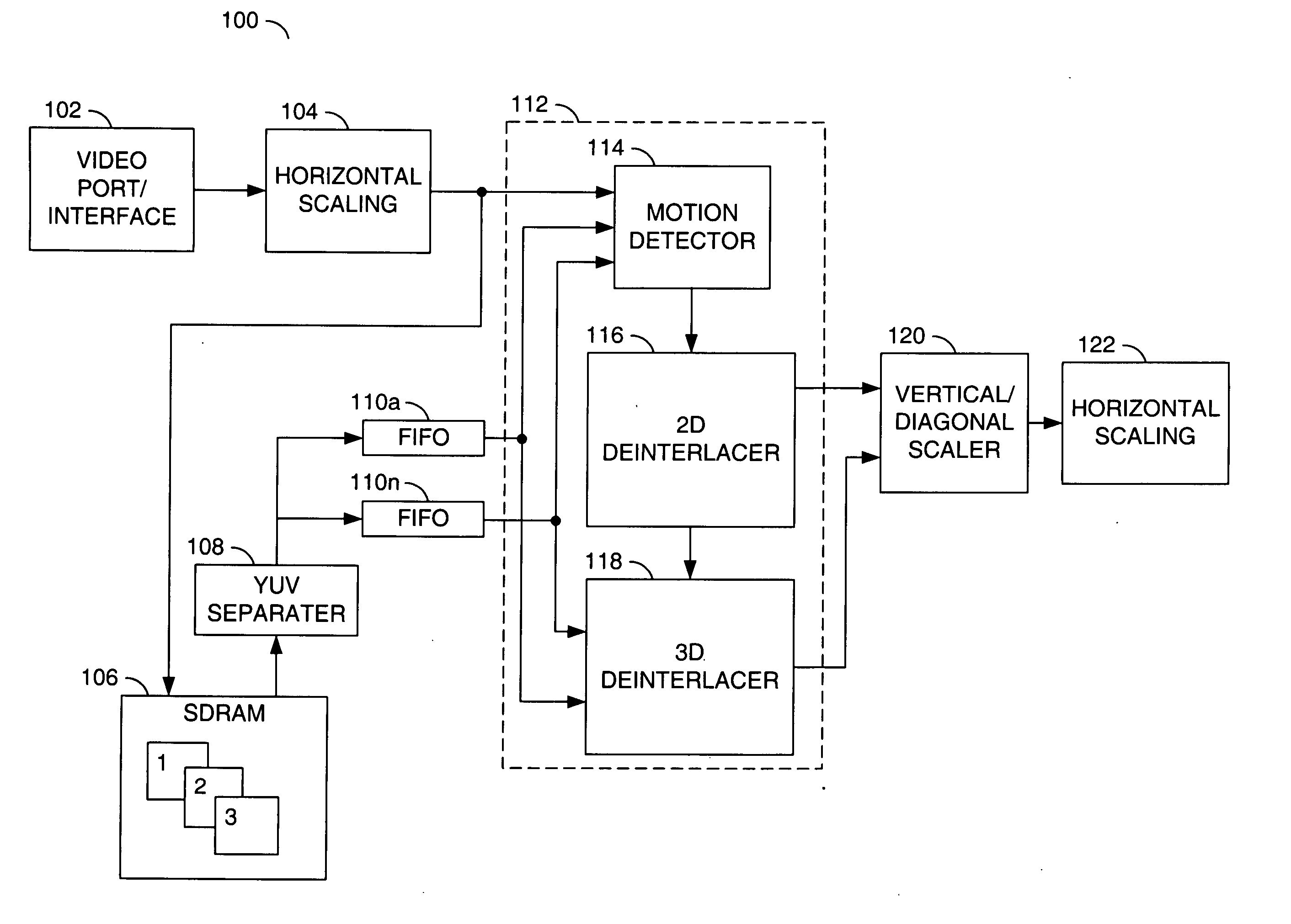
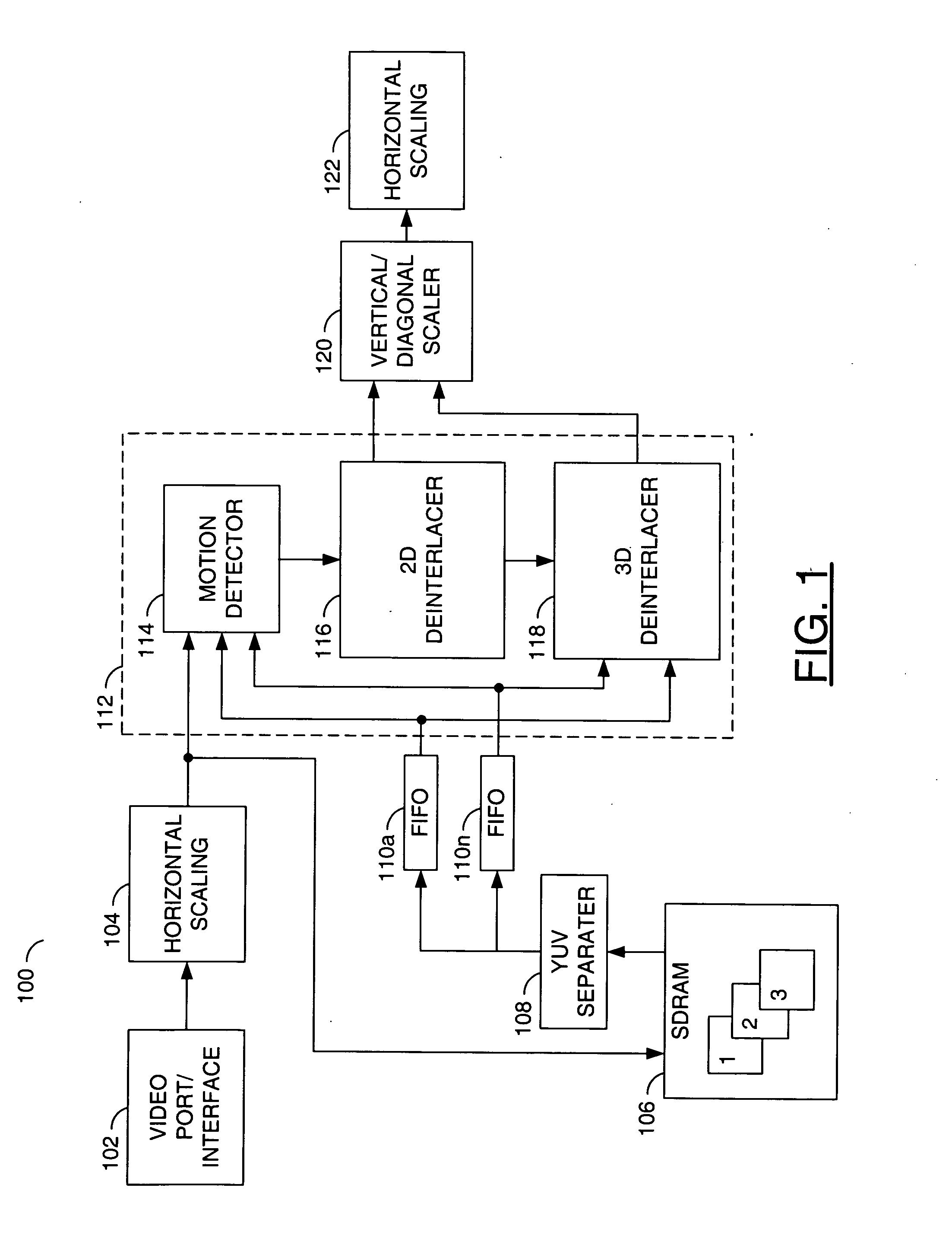
[0024] Referring to FIG. 1, a block diagram of a system 100 is shown illustrating an exemplary video deinterlacing system in which one or more preferred embodiments of the present invention may be implemented. In this exemplary configuration, video data may be presented to a port 102. The port 102 may be configured to send the video data to a horizontal scaling unit 104. The horizontal scaling unit 104 may be configured to scale the video data according to a predetermined factor in a first mode and pass the video data unscaled in a second mode. In one example, the horizontal scaling unit 104 may be configured to pass the video data directl...


PUM


Abstract

A method for rendering an object on a display screen, comprising the steps of (A) buffering a plurality of pixels in a plurality of line buffers, (B) determining a boundary of the object based on the buffered pixels, (C) determining a direction of the boundary, (D) testing if a pixel in the line buffers is in motion and applying one of a plurality of filter coefficients if the pixel is in motion, where the plurality of filter coefficients define a modified median filter having a predetermined threshold and (E) interpolating a new pixel in the direction of the boundary.

Description

FIELD OF THE INVENTION [0001] The present invention relates to a video processing generally and, more particularly, to systems and methods for deinterlacing video signals for digital display devices such as liquid crystal displays, plasma displays and progressive-scan televisions. BACKGROUND OF THE INVENTION [0002] Displaying video content originally created for television on a computer display is a desired feature for a multi-media computer system. However, television video signals and the computer video differ in formats. For example, many television and video signals are interlaced, where a set of scan lines of a single video frame are not scanned or transmitted sequentially. A typical U.S. NTSC (National Television System Committee) television signal uses two fields for each frame. Each field contains video data for every other horizontal line of the entire frame. Consecutive scans of the two fields occur 30 times per second. The scan lines for one field are transmitted first, f...

Claims


Application Information

Patent Timeline
Patent Type & Authority Applications(United States)
IPC IPC(8): H04N11/20
CPCG06T5/20H04N5/144H04N7/012G06T2207/20032G06T5/002G06T2207/10016G06T2207/10024H04N7/0137
Inventor WANG, HSI-CHENWANG, SHI-CHANG
Owner AVAGO TECH INT SALES PTE LTD
Why Eureka
Try Eureka