Micro-mechanical device, micro-switch, variable capacitor high frequency circuit and optical switch

a micro-mechanical device and high-frequency circuit technology, applied in the direction of generators/motors, relays, instruments, etc., can solve the problems of difficult to produce driving force separation, power supply expansion, and high cos

Inactive Publication Date: 2006-12-21
KK TOSHIBA
View PDF27 Cites 53 Cited by
  • Summary
  • Abstract
  • Description
  • Claims
  • Application Information

AI Technical Summary

Problems solved by technology

Therefore, there is a problem that the power supply has to be enlarged, and becomes very expensive.
If an electrode at a free end of the cantilevers and an electrode on a front surface of a substrate are in firm contact with each other, it is very difficult to produce driving force to separate them.
This will lead to a malfunction of the thin-film actuator.

Method used


Image

  • Micro-mechanical device, micro-switch, variable capacitor high frequency circuit and optical switch
  • Micro-mechanical device, micro-switch, variable capacitor high frequency circuit and optical switch
  • Micro-mechanical device, micro-switch, variable capacitor high frequency circuit and optical switch

Examples


first embodiment

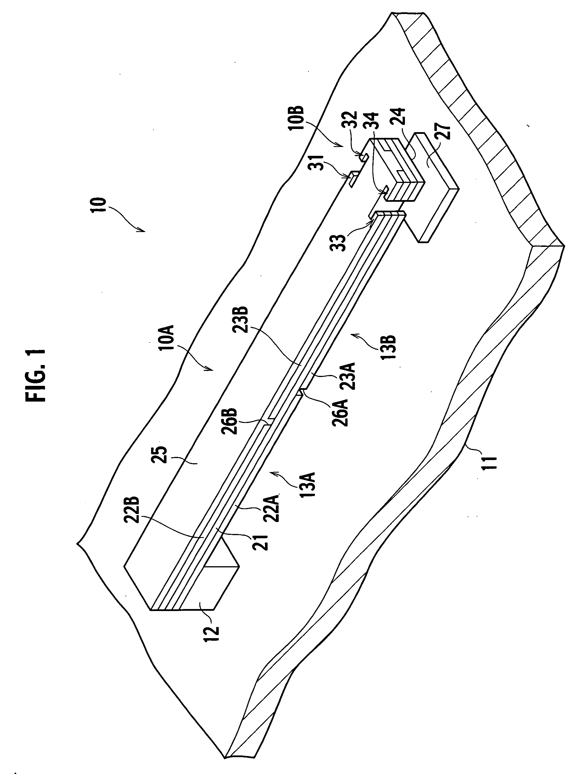
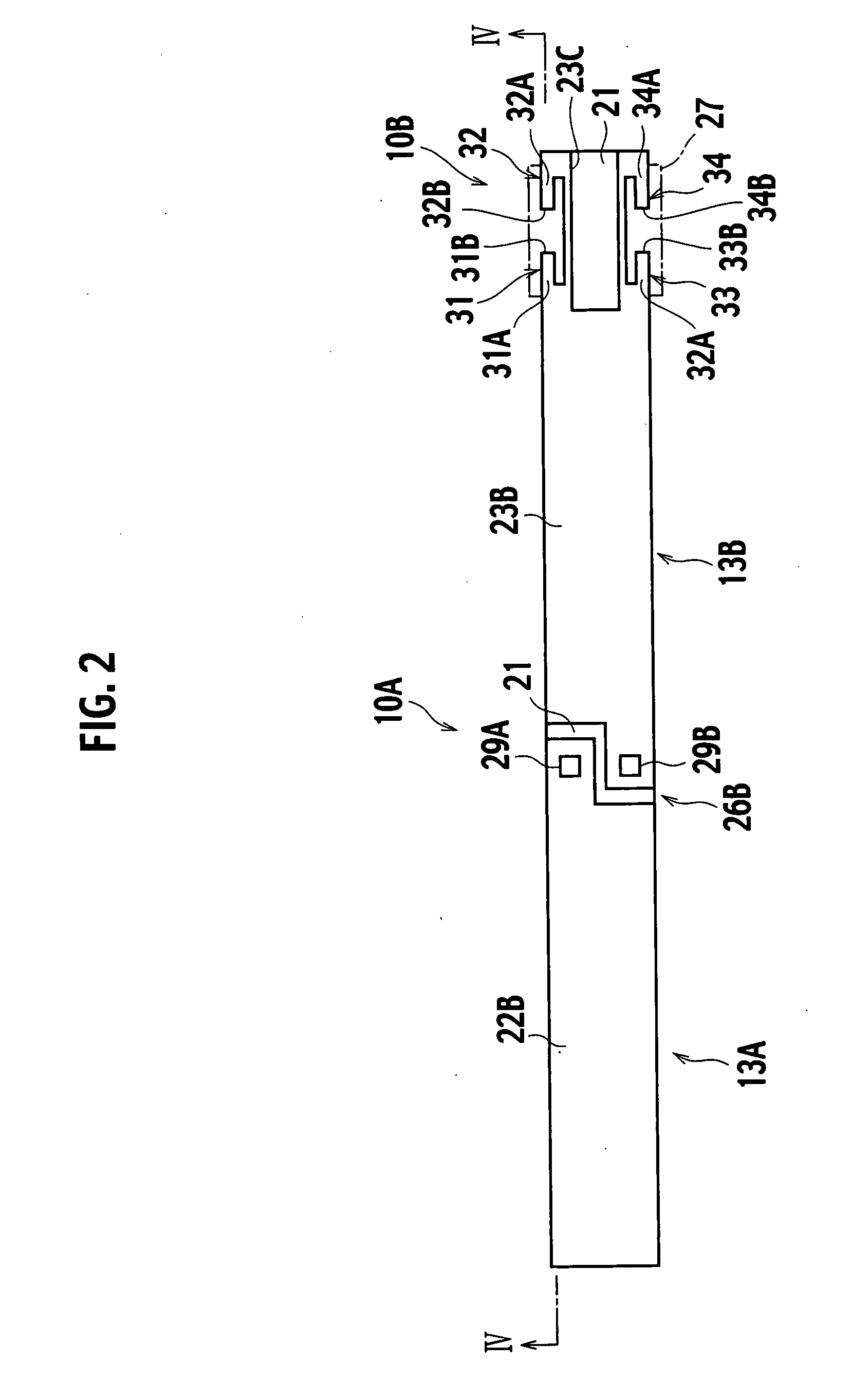
[0039] A micro-mechanical device 10 is applied as a micro-switch or like, and includes a main actuator 10A (a first piezoelectric actuator) in the shape of a cantilever, and a subsidiary actuator (a second piezoelectric actuator) 10B at an operating end (a first operating end) of the main actuator 10A.

[0040] Specifically, one end of the main actuator 10A is fixedly attached on a substrate 11 via an anchor 12 (a first fixing part). The main actuator 10A is constituted by a piezoelectric film 21, first and second lower electrodes 22A and 23A on the piezoelectric film 21 whose surface faces with the substrate 11, first and second upper electrodes 22B and 23B facing with the first and second lower electrodes 22A and 23A via the piezoelectric film 21, and a support film 25 provided on the first and second upper electrodes 22B and 23B. A slit 26A is formed between the lower electrodes 22A and 23A, and a slit 26B is formed between the upper electrodes 22B and 23B.

[0041] The subsidiary ac...

example 1

[0063] A specific example of the micro-mechanical device 10 will be described hereinafter.

[0064] A distance between the movable electrode 24 and the stationary electrode 27 should be 1 μm to 2 μm or longer in order to reliably insulate them during an off-time when the micro-mechanical device 10 is utilized as a high frequency switch in a gigahertz band.

[0065] The micro-mechanical device 10 includes a piezoelectric film 21 made of a c-axis-oriented aluminum nitride (AlN), first and second lower electrodes 22A and 23A and first and second upper electrodes 22B and 23B, both of which are made of aluminum (Al). The piezoelectric film 21 is 500 μm long, and 10 nm to 1 μm thick (preferably 500 nm thick). The lower and upper electrodes 22A, 23A, 22B and 23B are 10 nm to 1 μm thick (preferably 50 nm thick). A support film is made of SiO2, and is 50 nm thick.

[0066] When a +3V drive voltage is applied, a main actuator 10A bends, and the movable electrode 24 and the stationary electrode 27 a...

modified example

[0067] A modified example of the micro-mechanical device 10 is described with reference to FIG. 8 to FIG. 10. A subsidiary actuator 10B at the operating end of a main actuator 10A includes cantilevers 41 to 44, where a second lower electrode 23A, piezoelectric film 21, second upper electrode 23B and support film 25 are stacked one over after another. Ends of the cantilevers 41 to 44 serve as operating ends 41B to 44B via support points 41A to 44A. The cantilevers 41 to 44 are remarkably shorter than the main actuator 10A similarly to those in the micro-mechanical device 1 shown in FIG. 1.

[0068] The support points 41A and 42A are used both by the adjacent cantilevers 41 and 42, so that the operating end 41B (first operating end) and the operating end 42B (second operating end) face in opposite directions. Similarly, the support points 43A and 44A are used for the adjacent cantilevers 43 and 44, so that the operating end 43B (first operating end) and the operating end 44B (second ope...


PUM

PropertyMeasurementUnit
voltageaaaaaaaaaa
power voltageaaaaaaaaaa

Abstract

A micro-mechanical device includes a first piezoelectric actuator including a piezoelectric film, and lower and upper electrodes interleaving the piezoelectric film, and extending from a first fixing part on a substrate to a first operating end, and a second piezoelectric actuator connected to the first piezoelectric actuator via a connecting part at the first operating end of the first piezoelectric actuator, and extending from the connecting part to a second operating end, the second piezoelectric actuator being shorter than the first piezoelectric actuator.

Description

CROSS REFERENCE TO RELATED APPLICATIONS [0001] This application is based upon and claims the benefit of priority from prior Japanese Patent Application No. 2005-178,367 filed on Jun. 17, 2005; the entire contents of which are incorporated by reference herein. BACKGROUND OF THE INVENTION [0002] 1. Filed of the Invention [0003] This invention relates to a micro-mechanical device, a micro-switch, a variable capacitor, a high frequency circuit and an optical switch, and more particularly relates to a micro-mechanical device, a micro-switch, a variable capacitor, a high frequency circuit and an optical switch, all of which include piezoelectric actuators made of piezoelectric thin films. [0004] 2. Description of the Related Art [0005] There are thin-film actuators which are manufactured as micro-mechanical devices using the micro-electro-mechanical system (MEMS). Micro-switches, variable capacitors and so on including thin-film actuators are activated by electrostatic force. Specifically...

Claims


Application Information

Patent Timeline
Patent Type & Authority Applications(United States)
IPC IPC(8): G11B21/24
CPCB81B3/0021B81B2201/014B81B2201/045H01G5/40H01H2057/006H01G5/18G02B26/0858
Inventor KAWAKUBO, TAKASHINAGANO, TOSHIHIKOABE, KAZUHIDENISHIGAKI, MICHIHIKO
Owner KK TOSHIBA
Why Eureka
Try Eureka