Sterilization container latch mounting system

Active Publication Date: 2006-12-21
BAUER WITOLD
View PDF23 Cites 5 Cited by
  • Summary
  • Abstract
  • Description
  • Claims
  • Application Information

AI Technical Summary

Benefits of technology

[0007] The invention provides a support assembly for dual latch mechanisms for sterilization containers, said support assembly affording enhanced long-term structural integrity and sturdiness for repeated usage. It has been discovered that in addition to improved attachment integrity, a support assembly can be designed that utilizes significantly fewer components and materials. The invention also provides a support assembly that is directly attached or welded onto the container surface without relying on the use of intermediate coupling structures, such as studs, posts or plates, on the sterilization container exterior surface for fixation of the latch mechanism. The need for complex secondary structures between the latch mechanism and container surface to facilitate attachment is removed.
[0008] The invention is particularly useful in multi-component or complex latching mechanisms for sterilization containers wherein sturdy assembly and precise relationships between the various interacting components is directly related to its operational success. It has been further been discovered that the improved support assembly can also be easily configured to accommodate secondary structures, such as card holders and indicator arrows.

Problems solved by technology

One problem encountered with this support structure is mechanical failure.
Partially as a result of the number of couplings utilized in the assembly of the support structure of the Williams latch, the support assembly is susceptible to metal fatigue and separation of the support bar from the side of the container.
Consequently, the dual latch mechanism, which depends upon the secure fixation of the support structure, separates and becomes inoperative.
In turn, the barrier between the interior container environment and the exterior environment can be compromised.
Thus, even if the couplings of the support structure are loosened but not separated, the dual latch mechanism can be more difficult to operate due to the physical instability of the support assembly.

Method used


Image

  • Sterilization container latch mounting system
  • Sterilization container latch mounting system
  • Sterilization container latch mounting system

Examples


Embodiment Construction

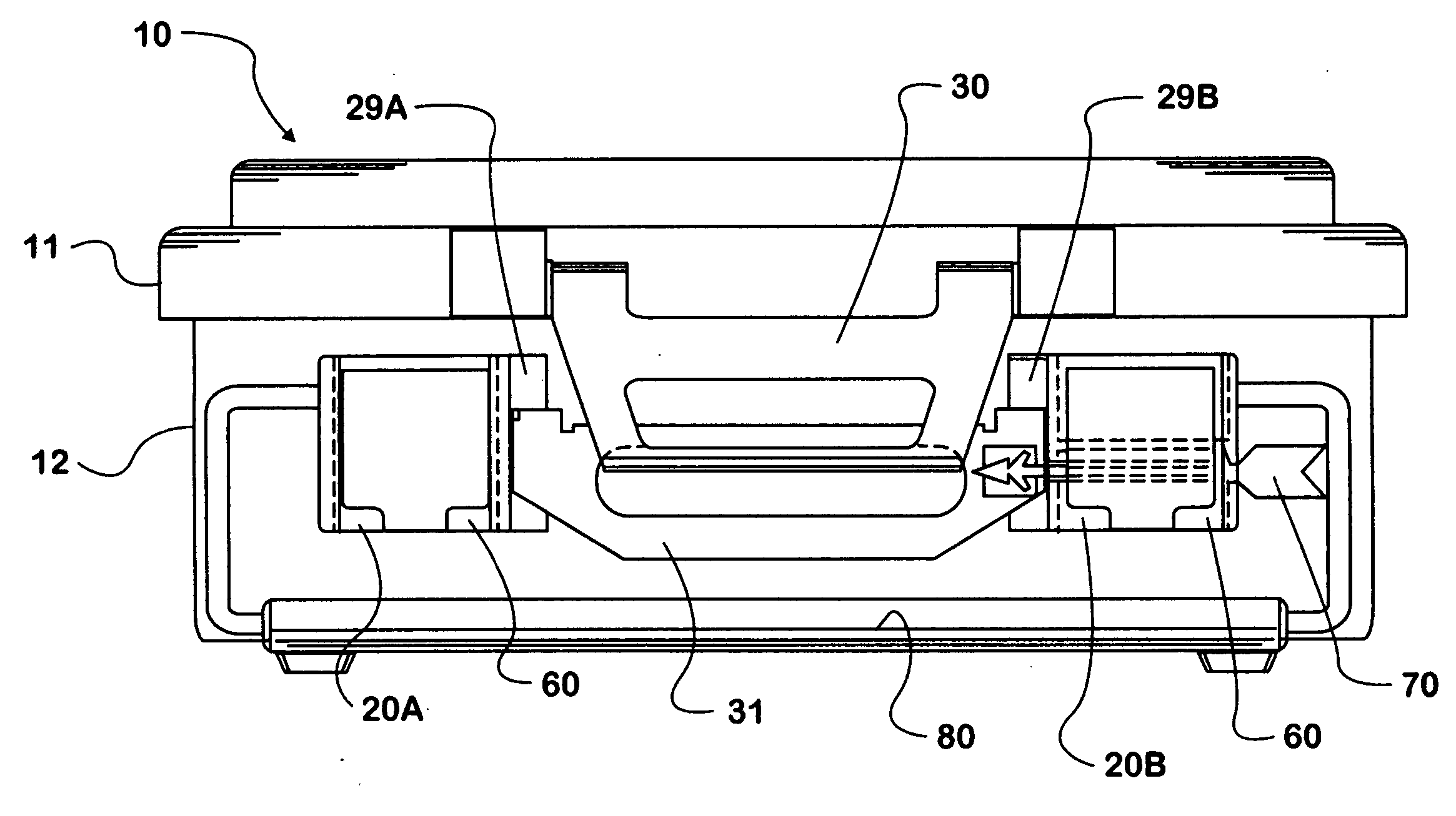
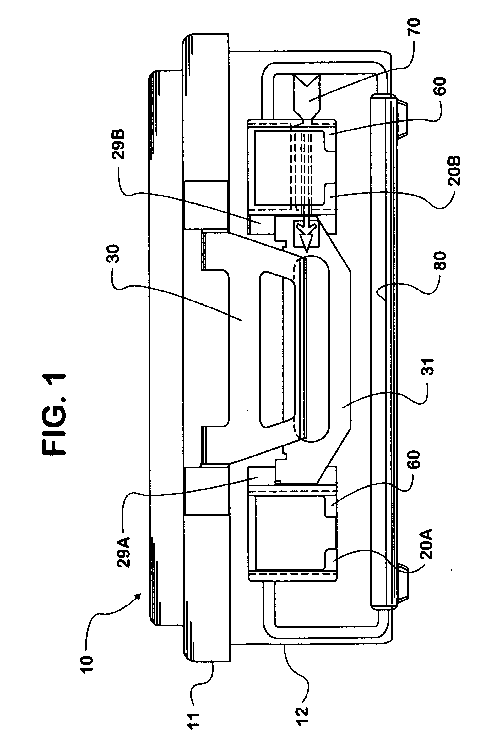
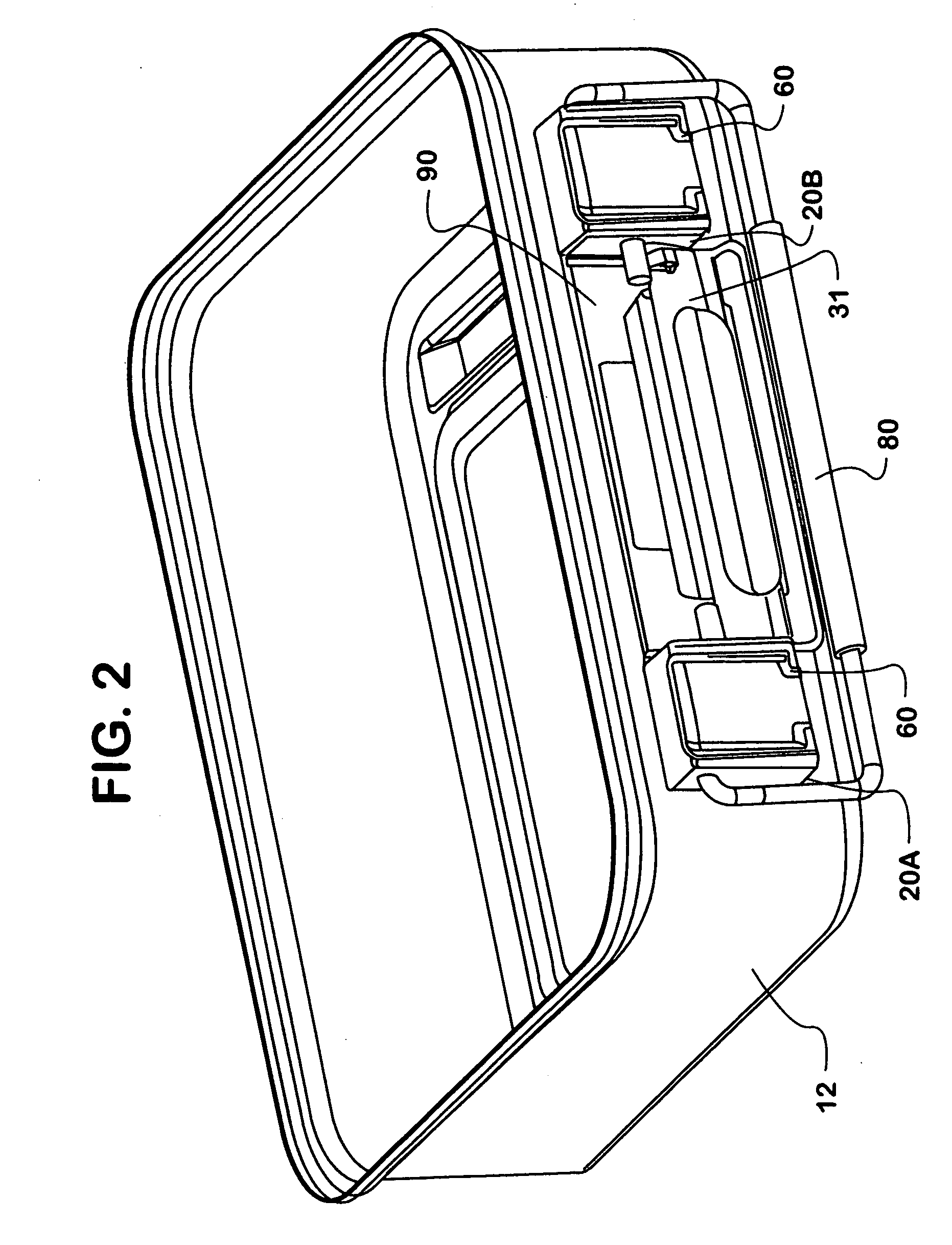
[0022] The invention can be used with sterilization container systems containing a lid component and tray component to be securely and removable attached to one another. Dual latch mechanisms, such as that described for use with the invention, provide a means to securely and removably engage the lid with the tray. The dual latch mechanism generally comprises an upper latch plate hingedly attached to the lid, and lower latch plate hingedly attached to the tray, wherein the upper latch plate and lower latch plate are structured to reversibly engage one another to secure the lid onto the tray. The improved support assembly of the invention can be used with the lower latch subassembly to enhance the sturdiness and precision of the dual latch mechanism as a whole, thereby improving its functionality and operation.

[0023] In general, one of the advantages of the invention is that the support assembly for the dual latch mechanism is attached or welded directly onto the exterior surface of ...


PUM


Abstract

The invention described herein includes a support assembly for a dual latch mechanism on a sterilization container, wherein the support assembly has improved structural rigidity and integrity for repeated usage. The support assembly comprises a pair of spaced apart blocks welded directly onto the exterior surface of the tray component of a sterilization container; wherein each of the blocks hingedly receive a lower latch plate of the dual latch mechanism. The invention further provides a dual latch mechanism for a sterilization container comprising the improved support assembly. The invention also provides a manufacturing process for sterilization containers having a lid component and tray component and dual latch mechanism, wherein the process comprises directly spot-welding two blocks in spaced apart position onto the exterior surface of the tray component.

Description

FIELD OF THE INVENTION [0001] The invention relates to the field of medical devices. In particular, the invention pertains to latching mechanisms used to secure lids and trays to one another in sterilization containers. BACKGROUND OF THE INVENTION [0002] A number of mechanisms to securely and removably attach lids to medical sterilization containers are known. A tightly sealed container system is important to the successful operation of medical sterilization containers, which should avoid compromise and entry of environmental contaminants upon removal of the container from an autoclave, for example. [0003] One such lid and tray attachment system is the dual latch system for sterilization containers as described in Williams et al., U.S. Pat. No. 4,915,913. The support structure described in Williams et al. is depicted in detail in FIGS. 15 and 16 of Williams et al. This latch system support structure includes an elongated rectangular portion having two outstanding or protruding end p...

Claims


Application Information

Patent Timeline
IPC IPC(8): A61L2/28E05C19/14B65D45/16
CPCA61L2/26E05C19/002E05C3/048A61L2202/24Y10T292/0871
Inventor BAUER, WITOLD
Owner BAUER WITOLD
Why Eureka
Try Eureka