Eureka AIR delivers breakthrough ideas for toughest innovation challenges, trusted by R&D personnel around the world.

Methods and apparatus for the prevention of incorrect card insertion

Inactive Publication Date: 2006-12-21
TELLABS OPERATIONS
View PDF21 Cites 1 Cited by
  • Summary
  • Abstract
  • Description
  • Claims
  • Application Information

AI Technical Summary

Benefits of technology

[0004] Embodiments of the present invention provide a system and method of ensuring proper insertion of circuit boards, communication modules, or other communication systems elements into a support assembly, such as a card cage or other chassis. In one embodiment of the present invention, a circuit board assembly includes a first keying feature located on the circuit board assembly at a location other than on a faceplate coupled to the circuit board assembly. The first keying feature may be integral with or coupled to a circuit board assembly notch, tab, or slot and the circuit board assembly may include at least one first component of a first connector assembly (e.g., pin-type connector). In this embodiment, the support assembly comprises a second keying feature and a second component of the connector assembly (e.g., socket-type connector), where the second component of the connector assembly may be located on a backplane in the support assembly. The second keying feature is positioned in a manner allowing circuit board assemblies with the correct keying feature to have the first component of the connector assembly connect with the second component of the connector assembly. The second keying feature prevents contact between the first connector component and the second component in cases where the circuit board assemblies lack the first keying feature or have the first keying feature misaligned from the second keying feature. As a result, embodiments of the present invention provide a cost-effective keying solution that prevents damage to circuit connectors and can be manufactured with relative ease.

Problems solved by technology

However, a particular backplane connector may not be compatible with a particular module's card connector(s).
If such a connection is made without regard to connector compatibility, an incorrect connection may result, possibly preventing desired communications or even damaging the system.
Moreover, a module intended to connect to the correct backplane connector may be oriented incorrectly, causing an improper connection, no connection, or damage to the connectors.

Method used


Image

  • Methods and apparatus for the prevention of incorrect card insertion
  • Methods and apparatus for the prevention of incorrect card insertion
  • Methods and apparatus for the prevention of incorrect card insertion

Examples


Embodiment Construction

[0012] A description of preferred embodiments of the invention follows.

[0013] Embodiments of the present invention determine and prevent incorrect card insertions prior to making connector component contact. Example embodiments are presented below in reference to FIGS. 1-4D. Based on the embodiments, cost savings of materials can be realized, and damage to connectors in the field may be reduced.

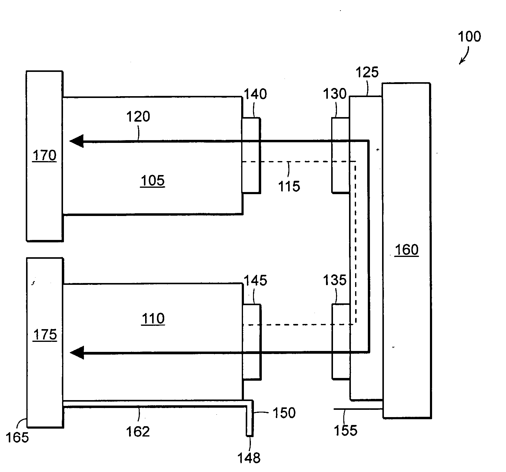
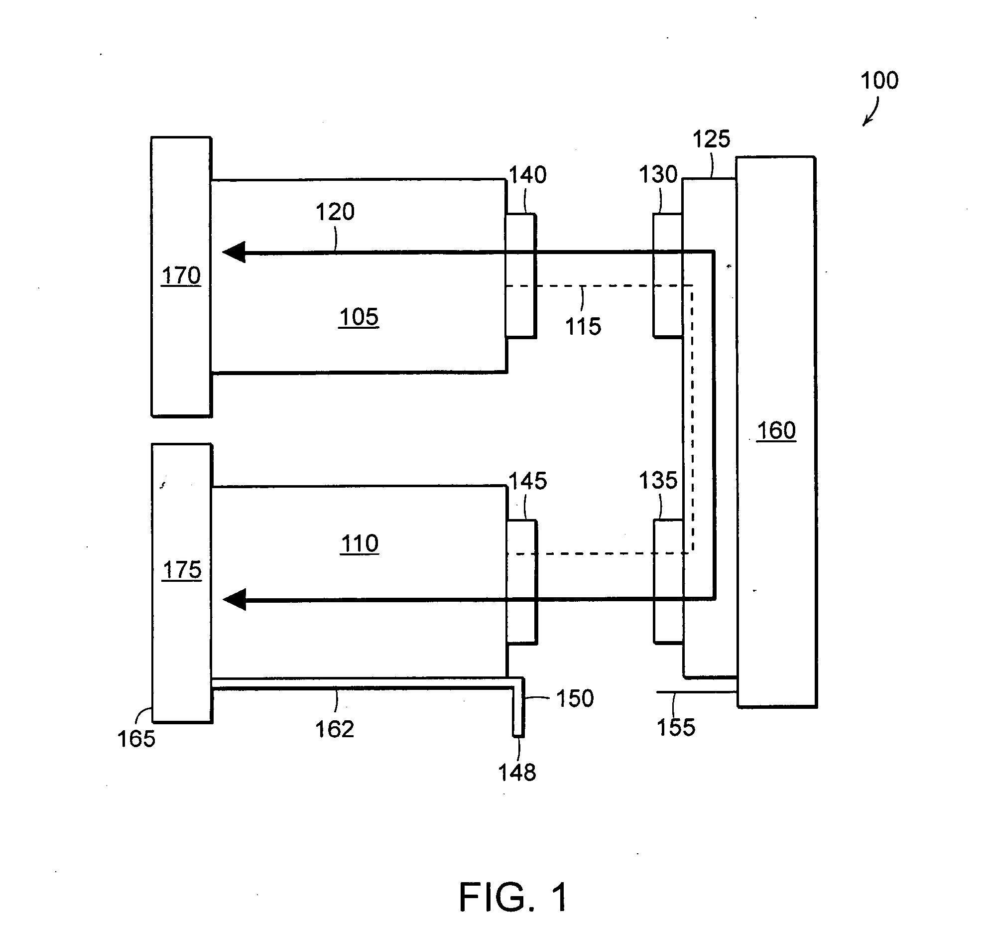
[0014]FIG. 1 is a mechanical diagram of a subsystem 100 in a communications system. The subsystem 100 includes communications modules 105, 110 (also referred to herein as “cards”) that connect to a multiple card-holding structure 160 (hereinafter referred to as a “chassis”). Within the chassis 160 is typically another card, a backplane 125, which may use socket-type connector components also referred to herein as “sockets,”130, 135 for receiving the cards 105, 110. At the edge of each card 105, 110 is a card connector component 140, 145, respectively, which are pin-type connector components...


PUM


Abstract

A system or method ensures proper insertion of a circuit board (“card”) assembly into a card support assembly. A card assembly includes a first keying feature other than on a faceplate connected to the card assembly. The keying feature may be a notch, tab or slot, and the keying feature may be integral with the card assembly. The card support assembly includes a second keying feature that corresponds to the first keying feature. The second keying feature is positioned so as to allow cards with the correct keying feature to connect with the support assembly and to prevent cards that lack the keying feature, or are misaligned, from contacting the connectors of the support assembly. As a result, an effective keying solution is provided for the card assembly, and damage to circuit boards and connectors caused by improper connections is prevented without costly manufacturing processes.

Description

RELATED APPLICATION(S) [0001] This application claims the benefit of U.S. Provisional Application No. 60 / 686,998, filed on Jun. 4, 2005. The entire teachings of the above application are incorporated herein by reference.BACKGROUND OF THE INVENTION [0002] Communications systems are typically modular in design, made of various communications modules that include hardware and software that transmit inter-module communications signals, such as data or clock signals, in order to support communications traffic running through the communications system. In such a communications system, several communications modules may connect to a chassis through which the modules send communications signals to one another. The chassis may include a backplane with a number of socket-type connectors, and the modules may include pin-type card connector(s). The card connector(s), if compatible with the chassis backplane connectors, mate with the backplane connectors, thereby connecting to the chassis backpl...

Claims


Application Information

Patent Timeline
IPC IPC(8): H01R24/00
CPCH01R13/6456
Inventor LOONEY, LYLE S.TOM, ALVAN R.
Owner TELLABS OPERATIONS
Why Eureka
Eureka Blog
Learn More