Injection compression moulding

a technology of injection compression and moulding rim, which is applied in the field of injection compression moulding, can solve the problems of difficult formation of rim closure ring, inability to form witness lines around the rim and limit the length to thickness ratio of the moulded articl

Inactive Publication Date: 2006-12-21
IM PAK TECH LTD
View PDF6 Cites 3 Cited by
  • Summary
  • Abstract
  • Description
  • Claims
  • Application Information

AI Technical Summary

Problems solved by technology

It has been found in practice, however, that it is difficult to form a rim closure ring with a cylindrical bore that effectively seals around the core and yet allows the core to pass freely through it.
The clearance required to permit reliable and free movement of the core relative to the rim closure ring does not permit creation of a perfect seal and results in an unacceptable witness line around the rim of the moulded article.
The above technique however places a limitation on the length to thickness ratio of the moulded article.
Injection compression moulding does however present certain problems that are not encountered in conventional injection moulding.
The first of the problems is concerned with the alignment of the mould parts.
However, before the mould is fully closed, the mould parts may not be fully aligned, that is to say they may not be concentric or they may not be co-axial.
The guiding that is achieved by...

Method used


Image

  • Injection compression moulding
  • Injection compression moulding
  • Injection compression moulding

Examples


Embodiment Construction

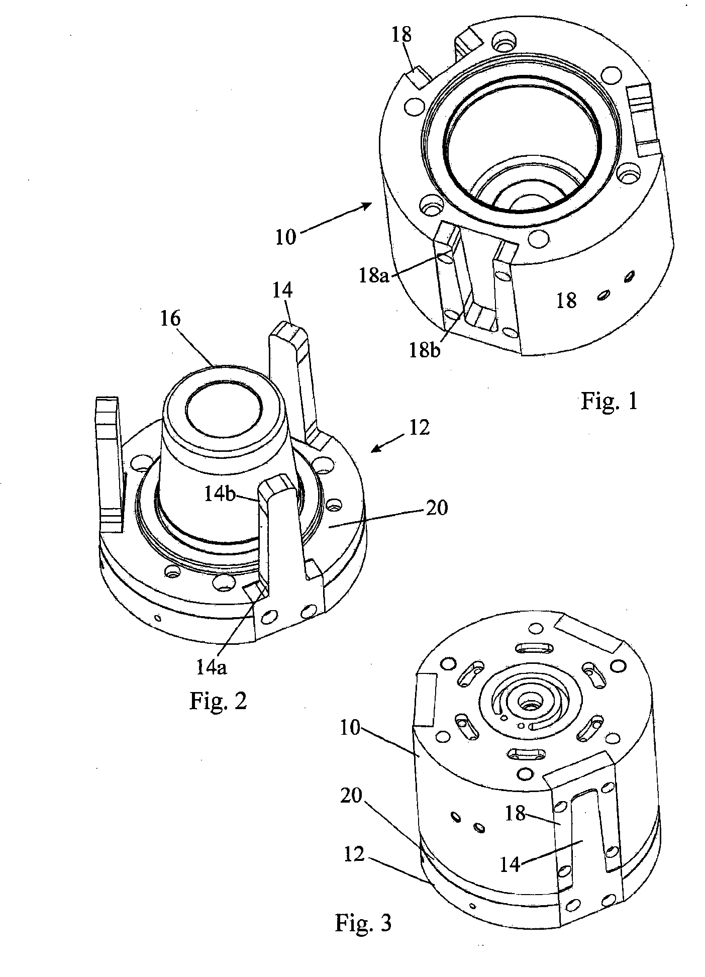
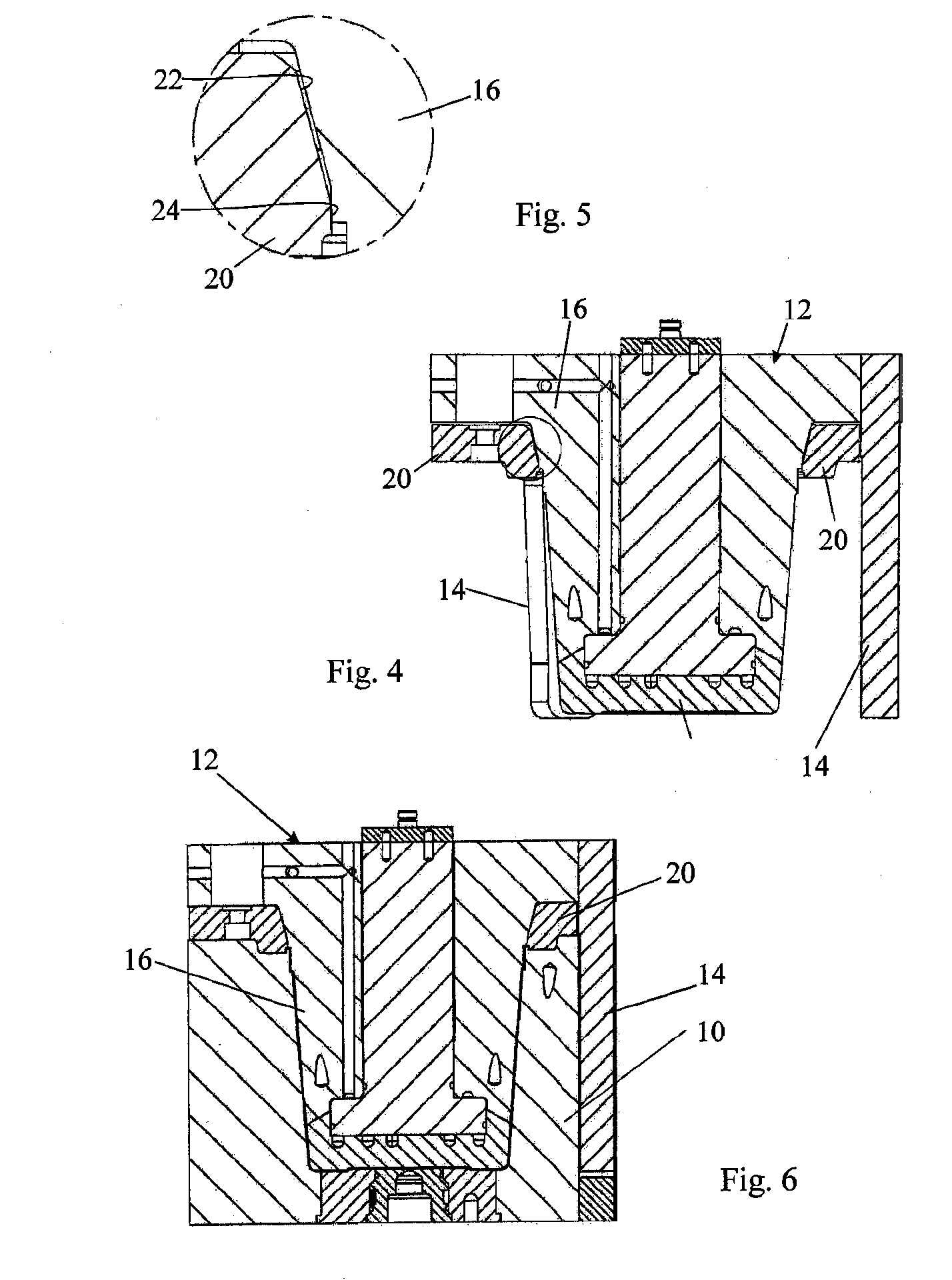
[0021] The figures show a single core / cavity set for an injection compression mould for making an article in the form of a drinking cup having a generally flat base, a frustro-conical side wall and a lip in the form of an inverted “U” surrounding the mouth of the cup. It will be appreciated that the core cavity / set may be one of many in a multi-cavity mould and that the different sets can be arranged side by side and / or stacked back to back. The ensuing description will, however, for simplicity, refer to a single cavity mould.

[0022] Referring to FIGS. 1, 2 and 3, the mould comprises a female mould part 10 and a core part 12 which fit into one another in the manner shown in FIG. 3 to leave between them a mould cavity having the desired shape of the drinking cup to be moulded.

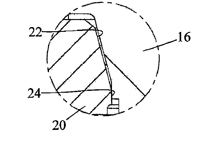
[0023] In the illustrated embodiment of the invention, three flat guide fingers 14 are firmly secured to the core part 12 to surround a central mould core 16 in accurately predetermined positions. Each of the g...


PUM

PropertyMeasurementUnit
Angleaaaaaaaaaa
Angleaaaaaaaaaa
Lengthaaaaaaaaaa

Abstract

A mould for injection compression moulding of an article includes a female mould part and a core for mounting in use on the platens of an injection moulding machine for movement towards and away from one another between an open and a closed position. A sealing ring surrounds the core for effecting a seal between the female mould part and the core. The core, the female mould part, and the sealing ring together define a closed mould cavity as the core approaches the closed position. The sealing ring has tapering sections, each tapering section having a tapering surface that seals against a tapering surface on the core only after the core has reached the closed position, leaving a venting clearance between the tapering surfaces of tapering sections of the sealing ring and the tapering surface of the core as the core approaches the closed position.

Description

RELATED APPLICATION [0001] This application is based upon and claims priority from prior British Patent Application No. 0400936.1, filed on Jan. 16, 2004 and PCT Patent Application No. PCT / GB04 / 005422 filed Dec. 30, 2004 the entire disclosures of which are hereby incorporated by reference in their entirety.BACKGROUND OF THE INVENTION [0002] 1. Field of the Invention [0003] The present invention relates to injection compression moulding and is concerned in particular with injecting a plastics material into a mould cavity. [0004] 2. Description of the Related Art [0005] In the injection compression moulding technique to which the present invention relates, an accurately measured quantity of plastics material is injected into a mould cavity before it has been fully closed. As the parts of the mould are brought together, the injected plastics material is compressed and made to fill the cavity by the force applied to close the mould rather than by the pressure applied to inject the plast...

Claims


Application Information

Patent Timeline
IPC IPC(8): F23L17/02B29C45/26B29C45/34B29C45/56
CPCB29C45/2606B29C45/2608B29C45/34B29L2031/7132B29C2045/4078B29L2031/712B29C45/561
Inventor CLARKE, PETER REGINALD
Owner IM PAK TECH LTD
Why Eureka
Try Eureka