Power situation indicator

a technology of power situation and indicator, which is applied in the direction of process and machine control, simultaneous indication of multiple variables, instruments, etc., can solve the problems of increased information overload, reported power loss, and pilots who do not have a true understanding of how close the power situation is to the limits of operation or authority

Active Publication Date: 2006-12-21
TEXTRON INNOVATIONS
View PDF1 Cites 36 Cited by
  • Summary
  • Abstract
  • Description
  • Claims
  • Application Information

AI Technical Summary

Benefits of technology

[0008] In an embodiment, there is provided a power situation indicator configured to provide power information in a rotorcraft, the rotorcraft including an engine, the power situation indicator including: a detection unit configured to detect a current value of each of a plurality of control parameters, each of the plurality of control parameters including a pre-determined operating limit; a calculation unit configured to normalize on a common power scale (a) the current value and (b) the pre-determined operating limit of each of the plurality of control parameters, and a display unit configured to dynamically display on the common power scale a first moveable indicator and a second moveable indicator, the first moveable indicator being driven by one of the plurality of control parameters having the highest normalized current value and said second moveable indicator being driven by one of the plurality of control parameters having its normalized current value that is the closest to its corresponding normalized pre-determined operating limit.
[0009] In another embodiment, there is provided a method of providing power information in a rotorcraft, the rotorcraft including an engine, the method including: detecting a current value of each of a plurality of control parameters, each of the plurality of control parameters including a pre-determined operating limit; normalizing on a common power scale (a) the current value and (b) the pre-determined operating limit of each of ...

Problems solved by technology

However, as more information becomes available, information overload has increased.
This, in turn, has increased the need for the information display to be intuitive, since any information that is presented “part time” is not afforded the luxury of continuous training through familiarity.
Statistics reveal that “internal loss of situation awareness” and “real-time aircra...

Method used


Image

  • Power situation indicator
  • Power situation indicator
  • Power situation indicator

Examples


Embodiment Construction

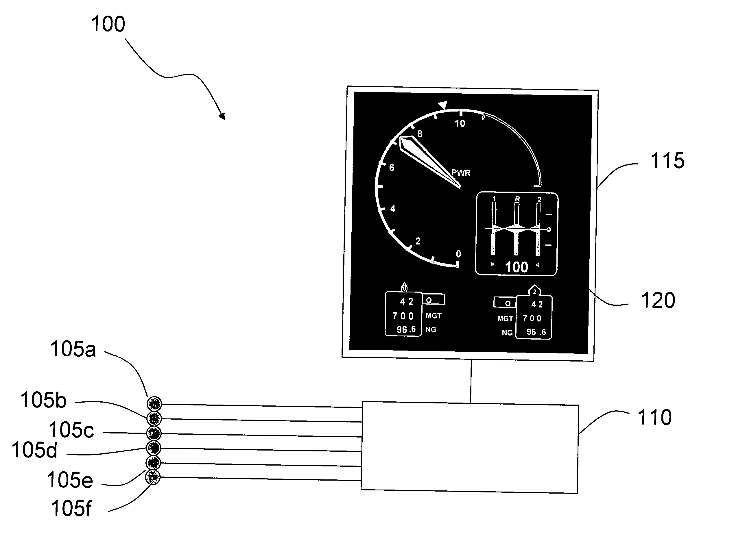
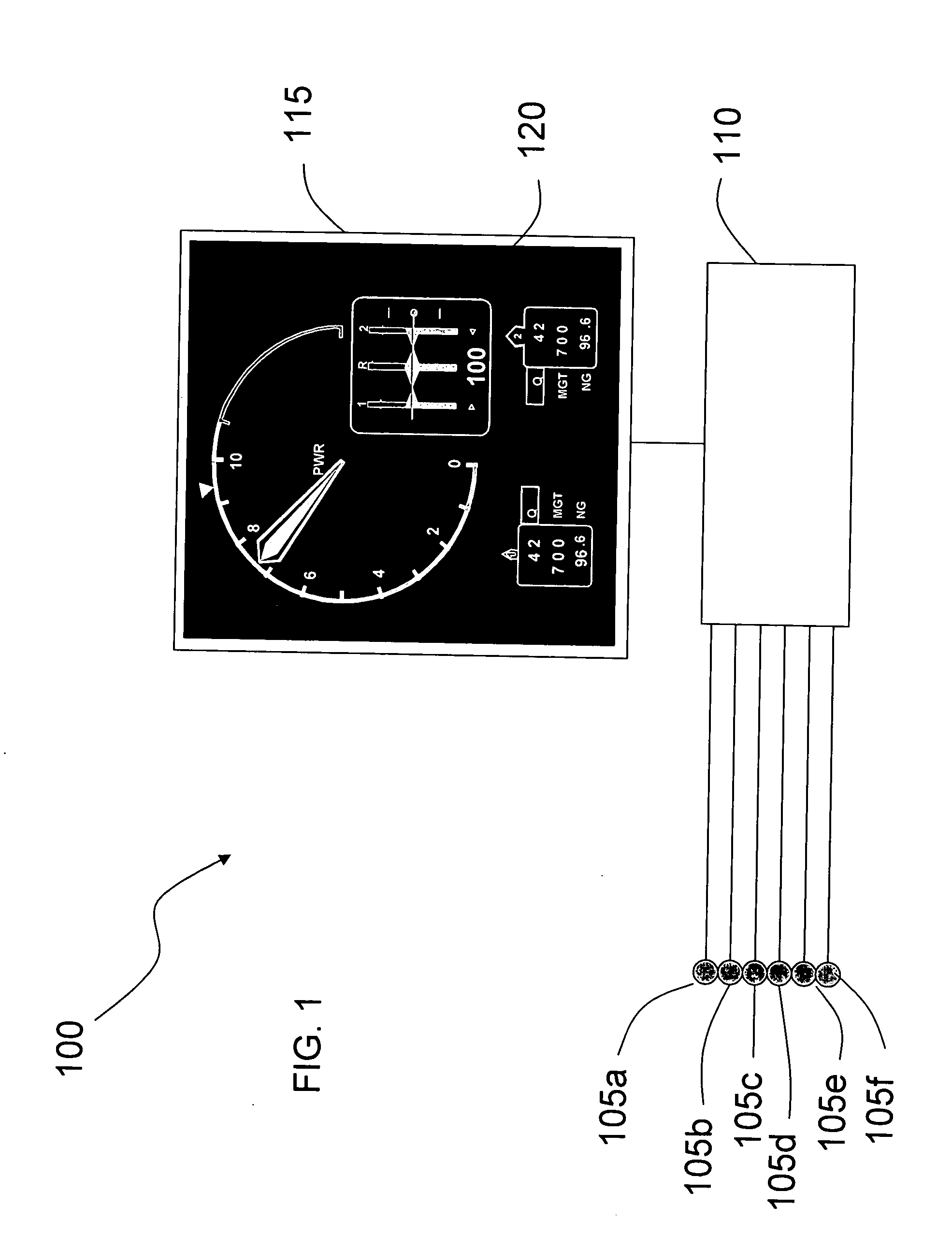
[0026] In the following embodiments of the invention, the Power Situation Indicator (PSI) will be described in conjunction with a rotorcraft (e.g., helicopter) with at least one turbine engine for driving at least one rotor. However, it will be appreciated that the PSI could be used in other types of aircraft.

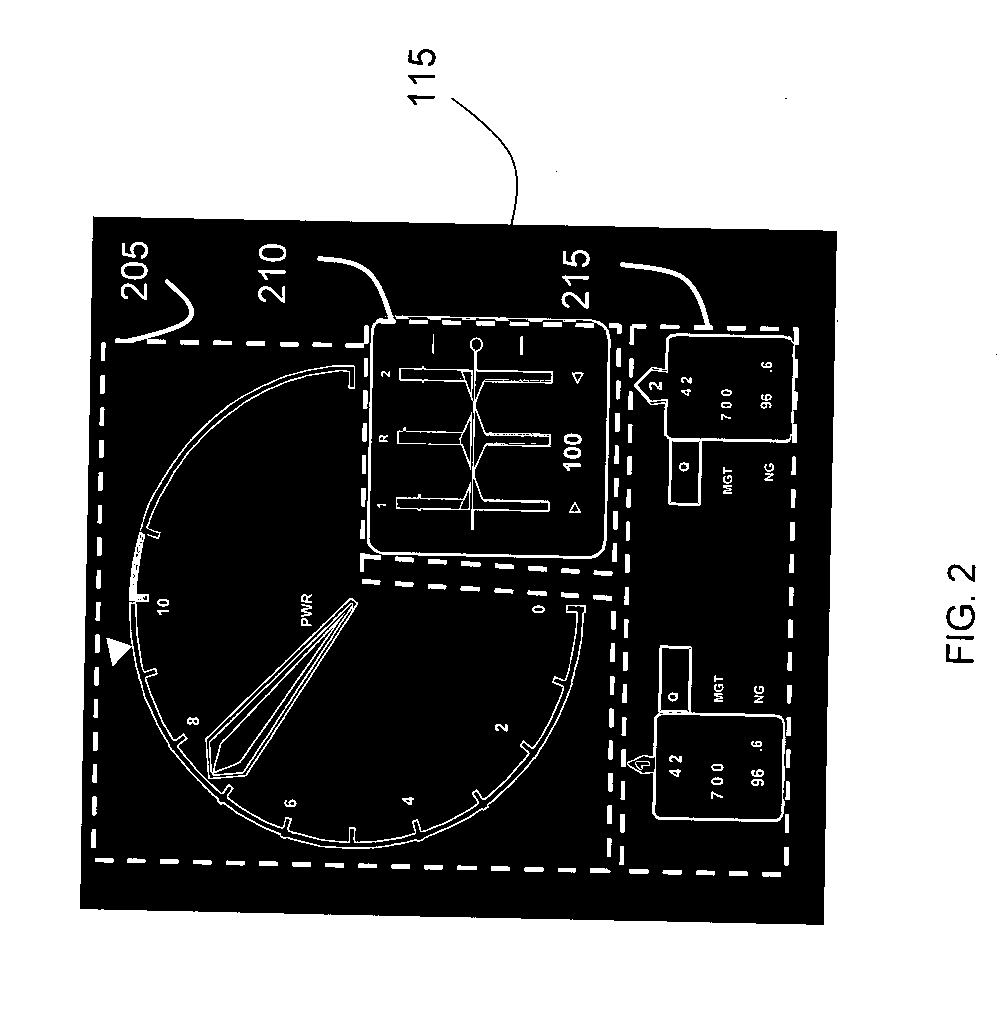
[0027] The power situation indicator (PSI) in embodiments of the present invention is configured to provide power indication as a function of flight conditions. Examples of flight conditions for a twin-engine rotorcraft include the all engine operative flight mode (AEO), one engine inoperative flight mode (OEI), non-governing modes (including preflight, run-up and shutdown), and autorotation. Examples of flight conditions for a single engine rotorcraft include the engine operative flight mode, non-governing modes (including preflight, run-up and shutdown), and autorotation.

[0028] In embodiments of the present invention, the PSI is constructed and arranged to replace the conve...


PUM


Abstract

A power situation indicator configured to provide power information in a rotorcraft is presented. The power situation indicator includes a detection unit configured to detect a current value of each of a plurality of control parameters, each of the plurality of control parameters including a pre-determined operating limit; a calculation unit configured to normalize on a common power scale (a) the current value and (b) the pre-determined operating limit of each of the plurality of control parameters, and a display unit configured to dynamically display on the common power scale a first moveable indicator and a second moveable indicator. The first moveable indicator is driven by one of the plurality of control parameters having the highest normalized current value and the second moveable indicator is driven by one of the plurality of control parameters having its normalized current value that is the closest to its corresponding normalized pre-determined operating limit.

Description

PRIORITY INFORMATION [0001] This application claims priority to Provisional Patent Application No. 60 / 647,384, filed Jan. 28, 2005, the content of which is incorporated herein by reference in its entirety.BACKGROUND [0002] 1. Field of the Invention [0003] The present invention relates to an aircraft power situation indicator. [0004] 2. Description of Related Art [0005] Flight instrumentation continues to improve, as more and more information becomes available. Terrain elevation data, mapping data, traffic avoidance, and weather information are examples of data that are now routinely provided to pilots during flight. However, as more information becomes available, information overload has increased. It is therefore desirable to limit the display of information only to when it is relevant. This, in turn, has increased the need for the information display to be intuitive, since any information that is presented “part time” is not afforded the luxury of continuous training through famil...

Claims


Application Information

Patent Timeline
IPC IPC(8): G06F17/00
CPCG01D7/002B60K37/02G01D7/02G01D2207/10B64D43/00
Inventor OLTHETEN, ERIKERWIN, JEFFERY
Owner TEXTRON INNOVATIONS
Why Eureka
Try Eureka