Sheet feeding device and image forming apparatus

a feeding device and a technology for forming apparatus, applied in the direction of instruments, manifolding, electrographic processes, etc., can solve the problems of insufficient flotation, enlargement of the entire apparatus, and difficulty for users to accurately set these, etc., to achieve high positional accuracy and high reliability

Inactive Publication Date: 2006-12-28
CANON KK
View PDF11 Cites 10 Cited by
  • Summary
  • Abstract
  • Description
  • Claims
  • Application Information

AI Technical Summary

Benefits of technology

[0012] The present invention has been achieved to solve the above described problem and an object of the invention is to provide a sheet feeding device capable of suppressing the deviation of sheet p...

Problems solved by technology

It is very difficult for user to set these accurately without any deviation in the sheet width direction.
As a result, when air is blown against a sheet, it might not be floated sufficiently enough to be fed.
If the quantity of blown air...

Method used


Image

  • Sheet feeding device and image forming apparatus
  • Sheet feeding device and image forming apparatus
  • Sheet feeding device and image forming apparatus

Examples


first embodiment

[First Embodiment]

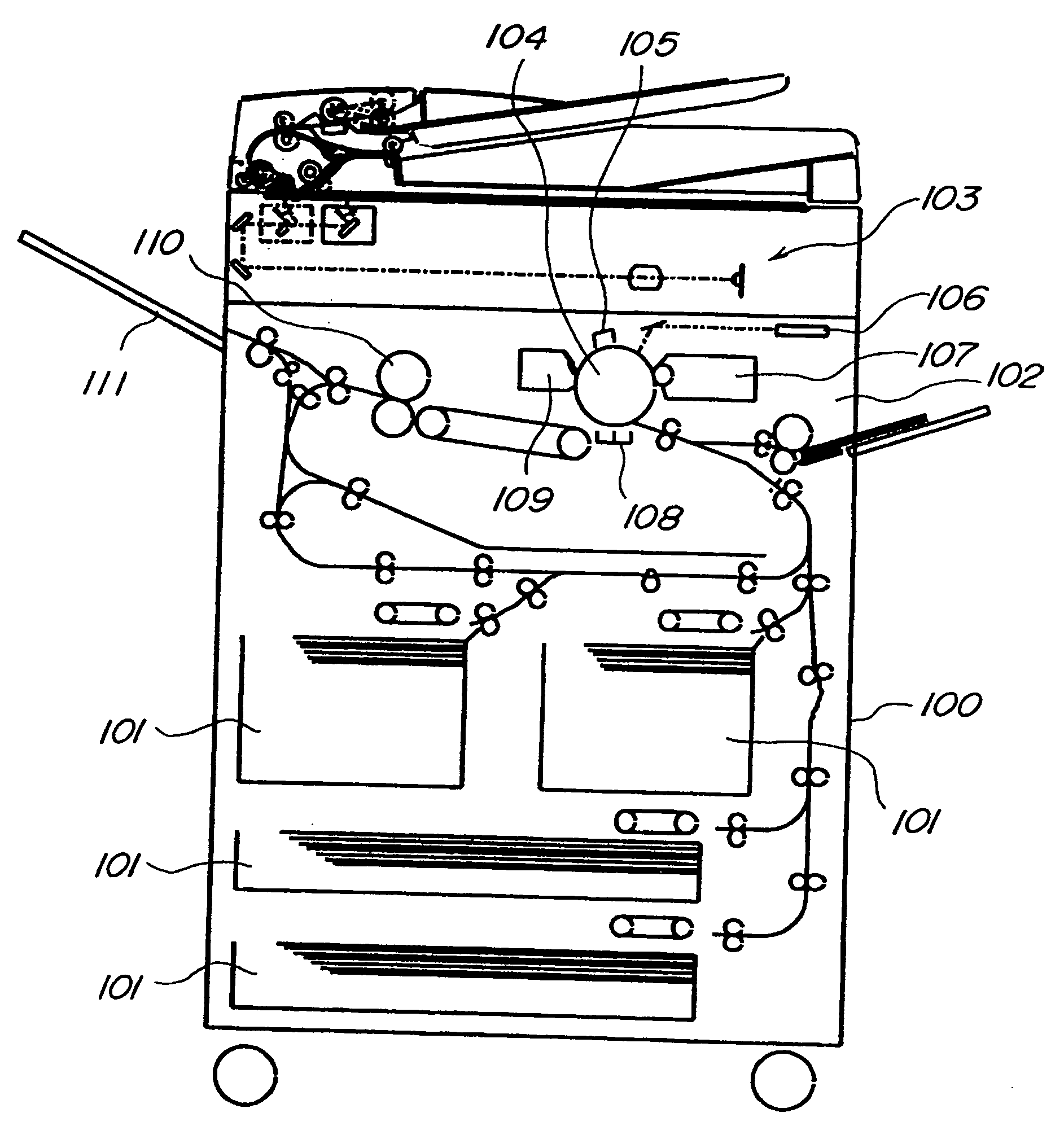
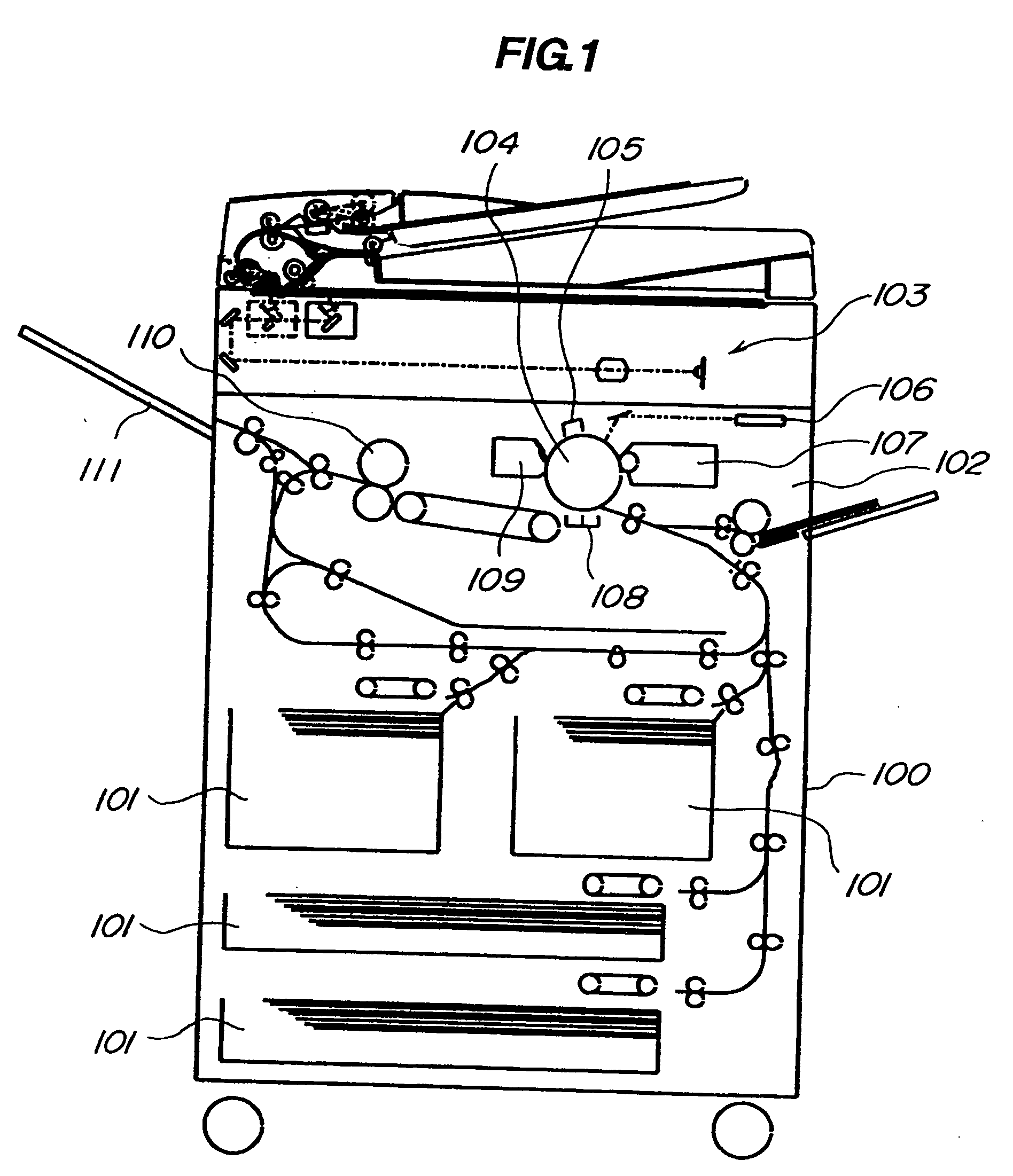
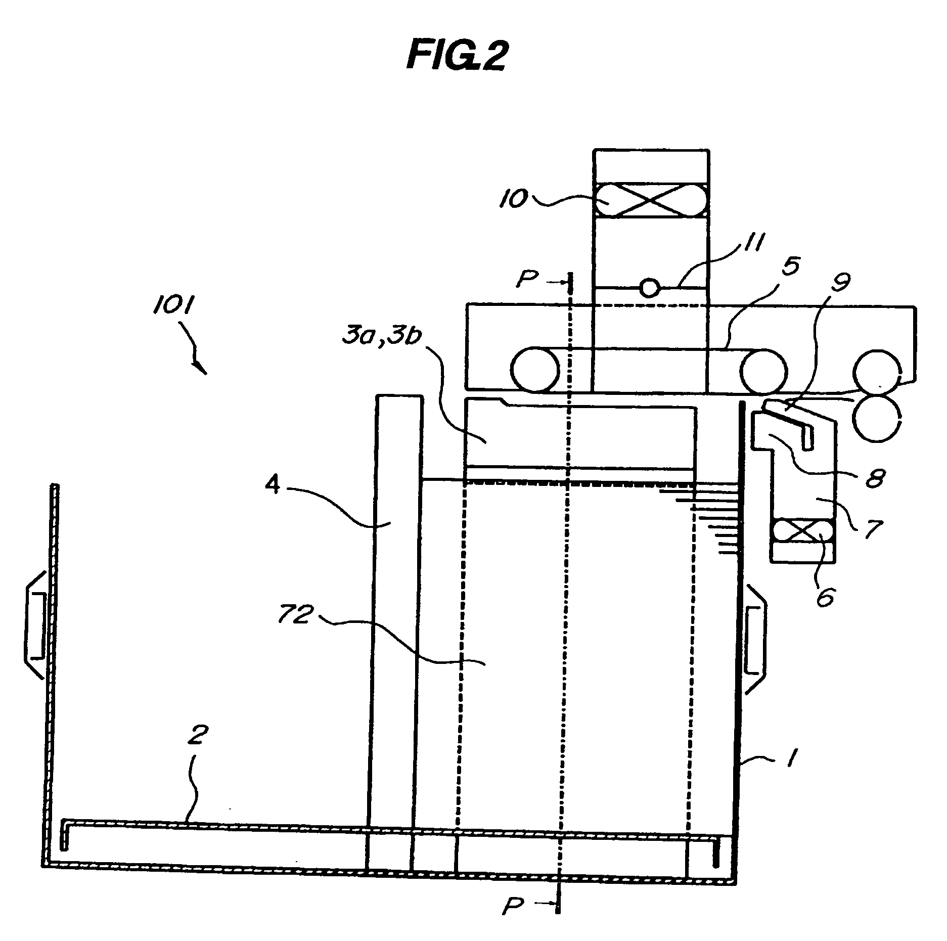
[0032]FIGS. 1-7 show the first embodiment. FIG. 1 is an entire schematic sectional explanatory diagram of the image forming apparatus. FIGS. 2-5 are explanatory diagrams of the air sheet feeding device. FIGS. 6, 7 are explanatory diagrams showing the characteristic portion of the air sheet feeding device.

[Image Forming Apparatus]

[0033] First, the entire structure of the image forming apparatus will be described. In the image forming apparatus of this embodiment, a sheet feeding device 101 is disposed at the bottom of the apparatus main body 100 and an image formation device 102 is disposed above it. Then, an image reading device 103 which reads an original optically and converts to electric signals is disposed at the topmost of the apparatus main body 100.

[0034] The sheet feeding device 101 is an air sheet feeding device, whose structure will be described in detail below. A sheet S fed from this sheet feeding device 101 is conveyed to the image formation device ...

second embodiment

[Second Embodiment]

[0055] The apparatus of the second embodiment will be described with reference to FIG. 8. Because the basic structure of the apparatus of this embodiment is the same as the first embodiment, duplicated description thereof is not explained and the structure characteristic of this embodiment will be described here. Further, like reference numerals are attached to components having the same function as the above-described embodiment.

[0056] In the sheet feeding device of this embodiment, of the side restricting plates 3a, 3b, the sheet opposing face of only one side restricting plate 3a is provided with the step portion 14 like the embodiment shown in FIG. 7 while the sheet opposing face of the other side restricting plate 3b is formed in a flat plane. According to this embodiment, a loosening fan 26 is disposed to blow air to the side end of the sheets in the sheet width direction perpendicular to the sheet feeding direction, in addition to the separation fan 6 (loo...

third embodiment

[Third Embodiment]

[0062] Next, the apparatus according to the third embodiment will be described with reference to FIG. 9. Because the basic structure of this embodiment is the same as the first and second embodiments, duplicated description thereof is not explained and the structure characteristic of this embodiment will be described. Same reference numerals are attached to components having the same function as the above-described embodiments.

[0063] In this embodiment also, the sheet opposing face of only one side restricting plate 3a is provided with the step portion 14 while the sheet opposing face of the other side restricting plate 3b (not shown in FIG. 9) is formed in a flat plane like the second embodiment. According to this embodiment, the loosening fan 26 is disposed to blow air in the sheet width direction perpendicular to the sheet feeding direction.

[0064] According to this embodiment, an auxiliary restricting plate 15 as a restricting member is provided at the step po...


PUM


Abstract

A sheet feeding device which feeds a sheet by loosening a sheet by loosening sheets by blowing air to the end portions of the sheets, comprising: a sheet tray provided to be capable of lifting up/down supporting the sheets; air blowing means which loosens the sheets by blowing air to the end portion at the topside of the sheets supported by the sheet tray; and a pair of restricting members which restricts both end portions in the direction perpendicular to the sheet feeding direction of the sheet with sheet opposing faces opposing the end portions of the sheets, wherein the interval between the sheet opposing faces at the top side of the pair of the restricting members is set larger than the interval between the sheet opposing faces below the position in which air is blown to the sheets with the air blowing means.

Description

BACKGROUND OF THE INVENTION [0001] 1. Field of the Invention [0002] The present invention relates to a sheet feeding device for feeding a sheet by loosening sheets by blowing air to a sheet stack and an image forming apparatus including the sheet feeding device. [0003] 2. Description of the Related Art [0004] As one of methods for feeding sheets one by one from sheet storage means (hereinafter referred to as storage compartment ) in an image forming apparatus such a printer, a copying machine, conventionally, an air sheet feeding device has been proposed. According to this method, as disclosed in Japanese Patent Application Laid-Open NO. 9-309624, gas (mainly, air) is blown to an end portion of a sheet stack to lift up plural sheets and separate them from each other and the sheet is carried while sucked with a conveyance belt. [0005] An example of the conventional air sheet feeding device will be described with reference to FIGS. 12, 13. FIG. 12 is a schematic sectional explanatory ...

Claims


Application Information

Patent Timeline
IPC IPC(8): B41F21/00
CPCB65H1/04B65H3/128G03G15/6511B65H2405/114B65H2405/15B65H3/48
Inventor IKEDA, TARO
Owner CANON KK
Why Eureka
Try Eureka