Ignition timing control device of internal combustion engine

Active Publication Date: 2006-12-28
TOYOTA JIDOSHA KK +1
View PDF3 Cites 30 Cited by
  • Summary
  • Abstract
  • Description
  • Claims
  • Application Information

AI Technical Summary

Benefits of technology

[0021] According to the present invention, it is possible to control ignition timing appropriately by suppressin

Problems solved by technology

Therefore, if the detected intensity values include intensity values of vibration of a noise component, a knocking occurrence

Method used


Image

  • Ignition timing control device of internal combustion engine
  • Ignition timing control device of internal combustion engine
  • Ignition timing control device of internal combustion engine

Examples


Embodiment Construction

[0040] Hereinafter, an embodiment of the present invention will be described with reference to the drawings. In the description below, same components are denoted by same reference numerals. Their names and functions are same. Therefore, detailed description thereof will not be repeated.

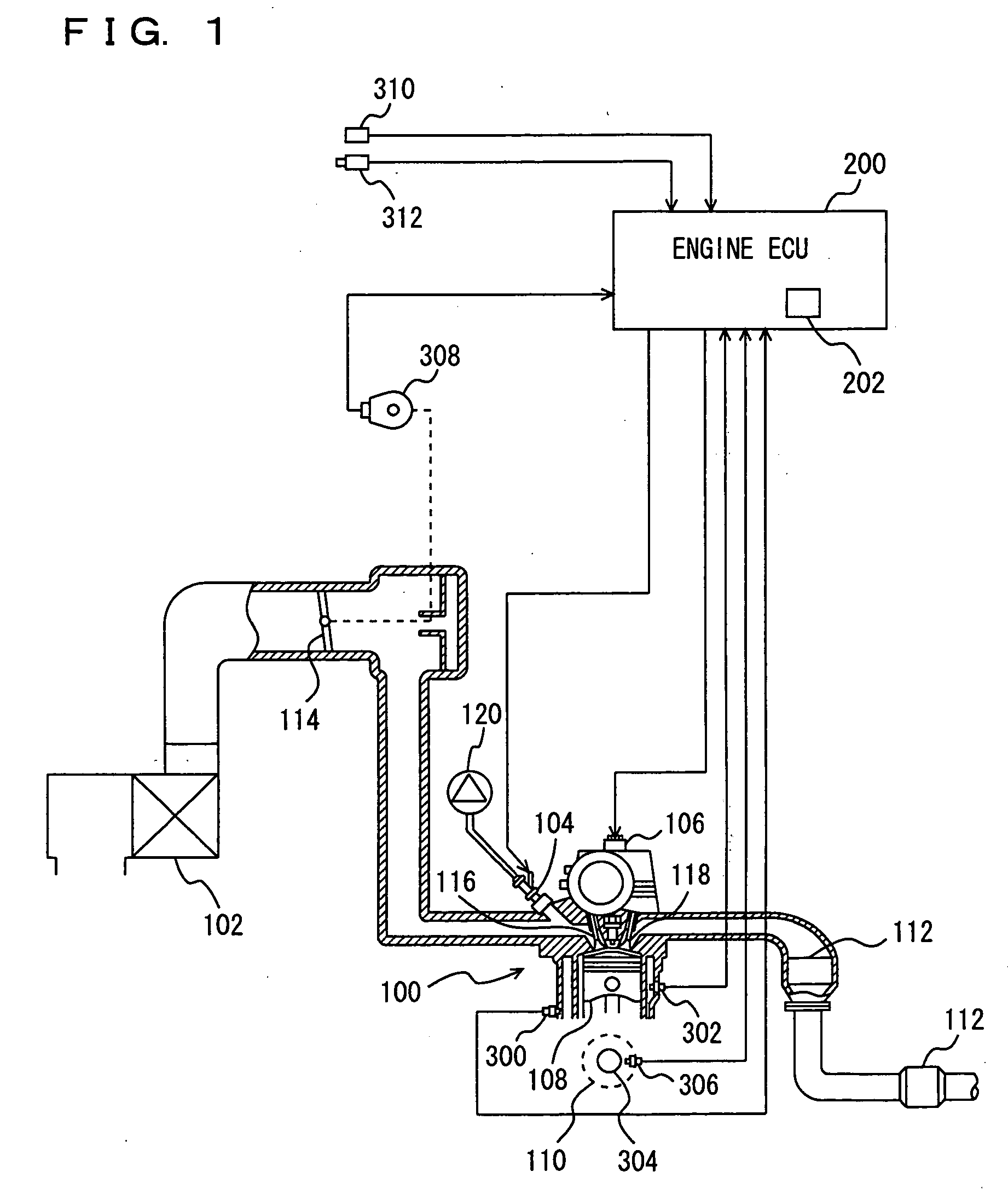
[0041] Referring to FIG. 1, an engine 100 of a vehicle mounting an ignition timing control device of an internal combustion engine according to an embodiment of the present invention will be described. The ignition timing control device of the internal combustion engine according to the present embodiment is realized by a program executed by an engine ECU (Electronic Control Unit) 200 for example.

[0042] Engine 100 is an internal combustion engine which ignites an air taken from an air cleaner 102 and an air-fuel mixture injected from an injector 104 with an ignition plug 106 in a combustion chamber and burns them. Injector 104 may be one which injects fuel into an intake manifold, or one which dire...


PUM


Abstract

An engine ECU executes a program including a step of calculating intensity values LOG(V), a step of detecting vibration waveforms, a step of calculating a correlation coefficient K based on vibration waveforms, a step of preparing frequency distribution of intensity values LOG(V) smaller than a threshold V(1) and intensity values LOG(V) in an ignition cycle where correlation coefficient K is larger than a threshold K(1), a step of calculating a knock determination level V(KD) based on a median V(50) and a standard deviation σ of intensity values LOG(V), and a step of counting the number of intensity values LOG(V) larger than knock determination level V(KD) as the number of times that knocking has occurred.

Description

[0001] This nonprovisional application is based on Japanese Patent Application No. 2005-188556 filed with the Japan Patent Office on Jun. 28, 2005, the entire contents of which are hereby incorporated by reference. BACKGROUND OF THE INVENTION [0002] 1. Field of the Invention [0003] The present invention relates to a technique for controlling ignition timing of an internal combustion engine, and in particular, to a technique in which a plurality of intensity values relating to the intensity of vibration of the internal combustion engine are detected, and based on the intensity values and the number (frequency) of each intensity value, ignition timing of the internal combustion engine is controlled. [0004] 2. Description of the Background Art [0005] In general, a knock determination level is set by multiplying an average value of knock sensor signals with a constant K. Such a KCS (Knock Control System) involves a problem that an optimum K value changes depending on manufacturing varia...

Claims


Application Information

Patent Timeline
IPC IPC(8): F02P5/152
CPCF02D35/027Y02T10/46G01L23/225F02P5/152Y02T10/40
Inventor KANEKO, RIHITOKASASHIMA, KENJIYOSHIHARA, MASATOMOASO, KOJISENDA, KENJIKAMIO, SHIGERUTAKEMURA, YUICHI
Owner TOYOTA JIDOSHA KK
Why Eureka
Try Eureka