
An ignition system for pulse detonation engine

A technology of pulse detonation and ignition system, applied in the field of ignition system, can solve the problems of affecting the operating frequency of the engine, large ignition delay time, and small spark plug ignition energy, so as to shorten the ignition delay time, shorten the time and distance, and increase the operating frequency Effect

Active Publication Date: 2019-02-05
JIANGSU UNIV
View PDF6 Cites 0 Cited by
  • Summary
  • Abstract
  • Description
  • Claims
  • Application Information

AI Technical Summary

Problems solved by technology

Weak ignition (spark plug ignition) is basically used in pulse detonation engines, while the ignition energy of traditional spark plugs is small, and the ignition delay time is large. For some non-explosive fuels, the DDT distance will be longer, which will affect the engine operating frequency.
In addition, pulse detonation engines work in extreme environments such as high temperature and high pressure, and the airflow velocity inside the detonation chamber is relatively high. Traditional spark plugs will have unstable ignition and low ignition success rate.
Plasma ignition and pre-detonation tube ignition can improve the performance of pulse detonation engines, but their equipment structure is relatively complex, it is difficult to miniaturize, and the system reliability is difficult to guarantee

Method used


Image

  • An ignition system for pulse detonation engine
  • An ignition system for pulse detonation engine
  • An ignition system for pulse detonation engine

Examples


Embodiment Construction

[0026] The present invention will be further described below in conjunction with the accompanying drawings and specific embodiments, but the protection scope of the present invention is not limited thereto.

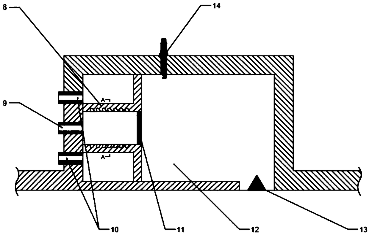
[0027] Such as figure 1 As shown, an ignition system for a pulse detonation engine includes a jet generator 1, a pulse detonation engine and a control system 7; the pulse detonation engine includes a detonation chamber 4, an air intake chamber 3 and an exhaust injection chamber 5. One end of the detonation chamber 4 communicates with the intake chamber 3, and the other end communicates with the tail spray chamber 5; the tail spray chamber 5 is provided with a gas detector 6 for detecting the gas concentration in the tail spray chamber 5; The jet generator 1 is installed on the detonation chamber 4 and is close to one end of the air intake chamber 3 .

[0028] Such as figure 2 As shown, the jet generator 1 includes a jet cavity 12 and a fuel chamber, a sealing plate is ...


PUM


Abstract

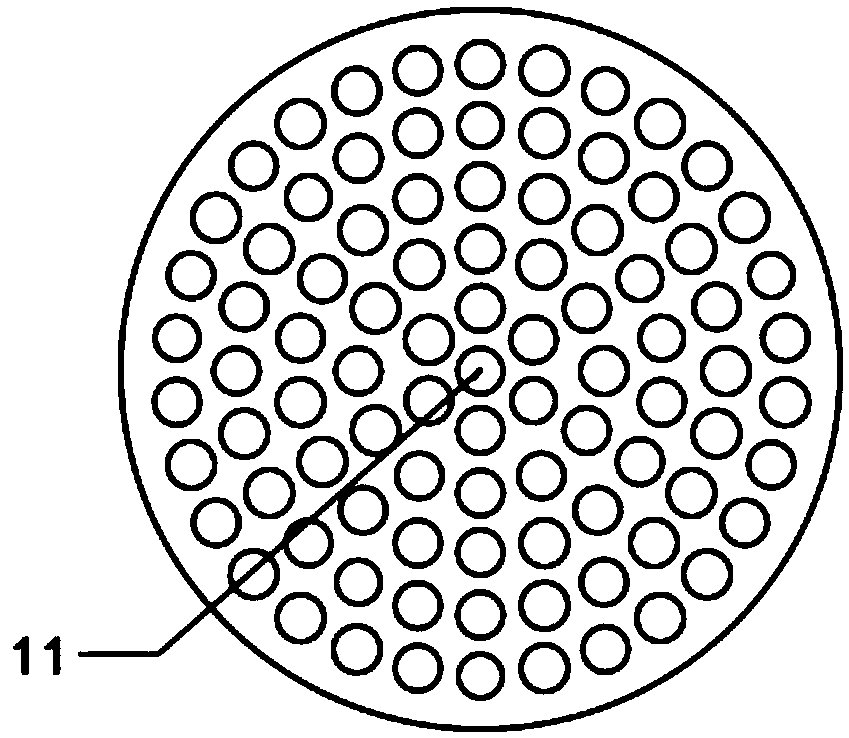
The invention provides an ignition system for a pulse detonation engine. The ignition system comprises a jet flow generator, the pulse detonation engine and a control system. The pulse detonation engine comprises a detonation chamber, an air inlet chamber and a tail spray chamber. The tail spray chamber is internally provided with a fuel gas detector, the jet flow generator comprises a jet flow cavity and a fuel chamber, and a sealing plate is arranged between the jet flow cavity and the fuel chamber. A swirler is mounted between the fuel chamber and the sealing plate, a first fuel gas chamberis internally provided with at least two fuel gas inlets, and a second fuel gas chamber is internally provided with an oxidant inlet. The swirler is a rotation body, a plurality of swirling holes areformed in the swirler, and a through hole is formed in the connecting position of the swirler and the sealing plate. The jet flow cavity is provided with an outlet, and the control system is connected with a sparking plug and the fuel gas detector. According to the ignition system for the pulse detonation engine, ignition energy of a detonation pipe can be increased, the DDT time and distance canbe effectively shortened, the time of the engine for completing one work cycle is shortened accordingly, and the work frequency and reliability of the engine are improved.

Description

technical field [0001] The invention relates to the field of aeroengines, in particular to an ignition system for a pulse detonation engine. Background technique [0002] Pulse detonation engine is a new concept propulsion system based on detonation combustion. Compared with conventional gas turbines or ramjet engines, pulse detonation engines have the advantages of high thermal efficiency, low fuel consumption, simple structure, wide operating range, and low cost of use and maintenance. It is one of the ideal power sources for future advanced aerospace vehicles. [0003] Detonation combustion is the basis of pulse detonation engine, and the triggering of detonation wave is the core technology of pulse detonation engine. There are usually two ways to detonate a pulse detonation engine: direct detonation and indirect detonation. It is impractical to directly trigger the detonation wave with high energy in the actual operation process. The feasible method is to first generat...

Claims


Application Information

Patent Timeline
Patent Type & Authority Patents(China)
IPC IPC(8): F02C7/266F02C5/00
Inventor 姜超潘剑锋李剑星潘振华朱跃进
Owner JIANGSU UNIV
Learn More