

Vehicle body structure
a technology for vehicles and body parts, applied in the direction of electric devices, battery/fuel cell control arrangements, electric devices, etc., can solve the problems of reduced rear trunk capacity, inability to efficiently accommodate electric storage devices, and increased structure size in front/rear direction, so as to reduce the wind resistance created during vehicle travel
- Summary
- Abstract
- Description
- Claims
- Application Information
AI Technical Summary
Benefits of technology
Problems solved by technology
Method used
Image

Examples
Embodiment Construction
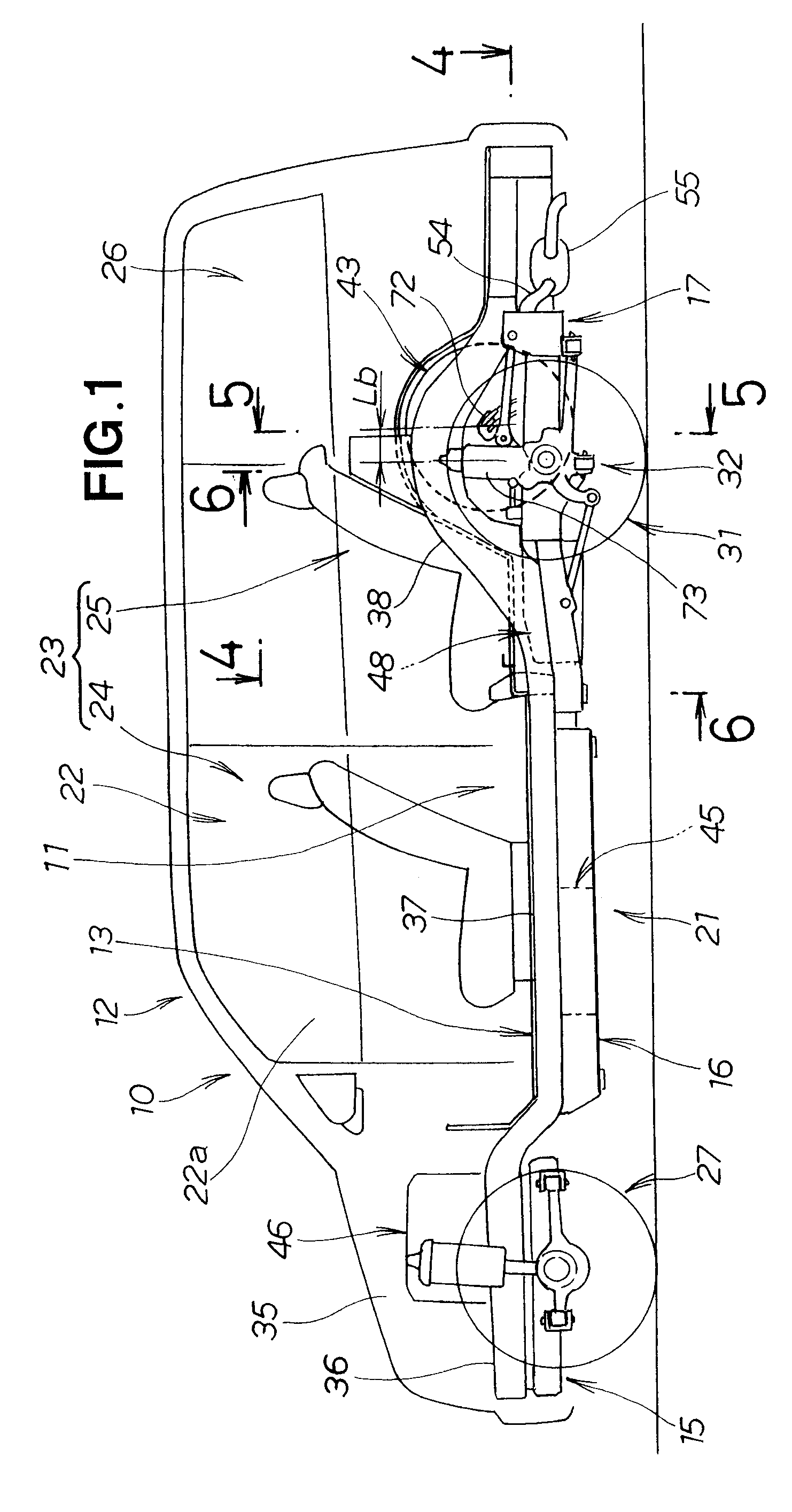
[0036] The vehicle 10 shown in FIG. 1 is a fuel cell vehicle. The vehicle 10 is provided with the vehicle body structure 11 of the present invention, a fuel cell system 21, seats 23 comprising a front seat 24 and a rear seat 25 disposed in the vehicle interior 22, a luggage compartment 26, front wheels 27, rear wheels 31, and a rear suspension 32. The front seat 24 is disposed in the cabin 22a of the vehicle interior 22.
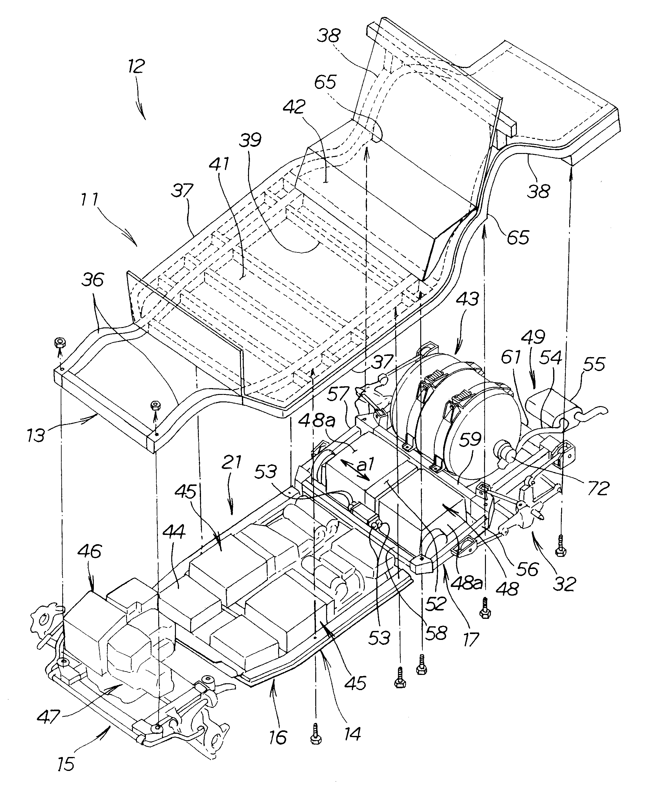
[0037] The vehicle body structure 11 constitutes a portion of the vehicle body 12 and comprises a vehicle body frame 13 that extends in the front / rear direction of the vehicle 10, and a subframe 14 mounted in the lower portion of the vehicle body frame 13. The subframe 14 comprises a front subframe 15, an intermediate subframe 16, and a rear subframe 17.
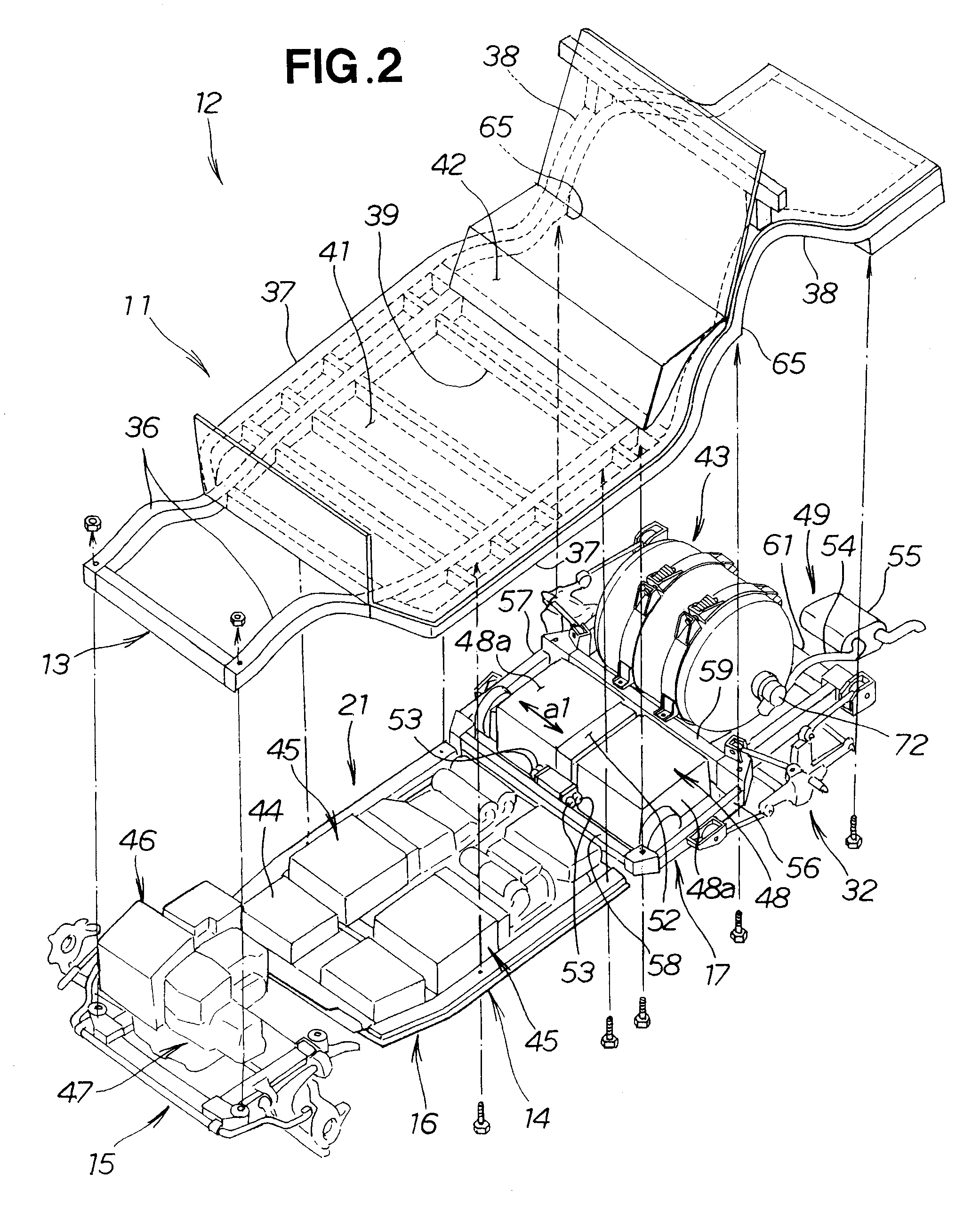
[0038]FIG. 2 shows a vehicle body frame 13 provided with the vehicle body structure 11 of the present invention.
[0039] The vehicle body frame 13 is provided with left and right side frames 36 and 36, left and right...
PUM
 Abstract
Description
Claims
Application Information