Fogging detecting system for an automotive vehicle and method for controlling the system

a detection system and automotive technology, applied in vehicle maintenance, vehicle cleaning, transportation and packaging, etc., can solve the problems of inability to know the temperature distribution, inaccurate calculation of dew point temperature, and decreased accuracy and responsive properties, so as to prevent the decrease of fuel efficiency and prevent unnecessary effects

Active Publication Date: 2006-12-28
HANON SYST
View PDF4 Cites 45 Cited by
  • Summary
  • Abstract
  • Description
  • Claims
  • Application Information

AI Technical Summary

Benefits of technology

[0015] Therefore, the present invention has been made in view of the above problems occurring in the prior art, and it is an object of the present invention to provide a defogging system and a method for controlling the same, which can prevent the decrease of the fuel efficiency due to the operation of the defogging system, by calculating the dew point temperature through estimating the volume of the peripheral vapor more accurately based on the temperature fluctuation of the wind shield glass at first, and then expecting the time of the occurrence of the fog to be closer to the actual time of the occurrence of the fog to thereby prevent the unnecessary operation of the defogging system.

Problems solved by technology

However, most of the fog sensors calculate the dew point temperature only on the basis of the surface temperature of the wind shield glass, or only on the basis of the peripheral temperature of the wind shield glass, so that the accuracy of the calculation of the dew point temperature is doubted.
However, the fog sensor unit calculates the dew point temperature by measuring the temperature with the air temperature sensor only, and the glass temperature sensed by the glass temperature sensor is not used in the calculation of the dew point temperature.
Accordingly, it is impossible to know the temperature distribution depending on the air conditioning and the state of the vehicle, so that the accuracy and the responsive property were decreased at the time of expecting the occurrence of the fog, when the fluctuation of the temperature is serious due to outer disturbances such as the air fluctuation at the inside of the vehicle, and the like.

Method used


Image

  • Fogging detecting system for an automotive vehicle and method for controlling the system
  • Fogging detecting system for an automotive vehicle and method for controlling the system
  • Fogging detecting system for an automotive vehicle and method for controlling the system

Examples


Embodiment Construction

[0035] Reference will now be made in detail to the preferred embodiment of the present invention with reference to the attached drawings.

[0036] The terms and words used in the description of the present invention should be construed as meanings and concepts conforming to the technical spirit of the present invention based on the principle that the inventor can define the concept of the term appropriately to explain his invention in best way.

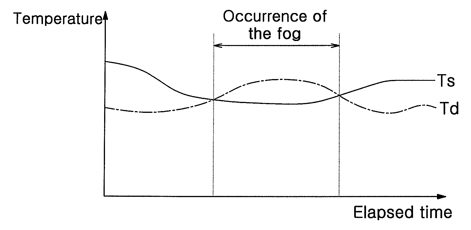
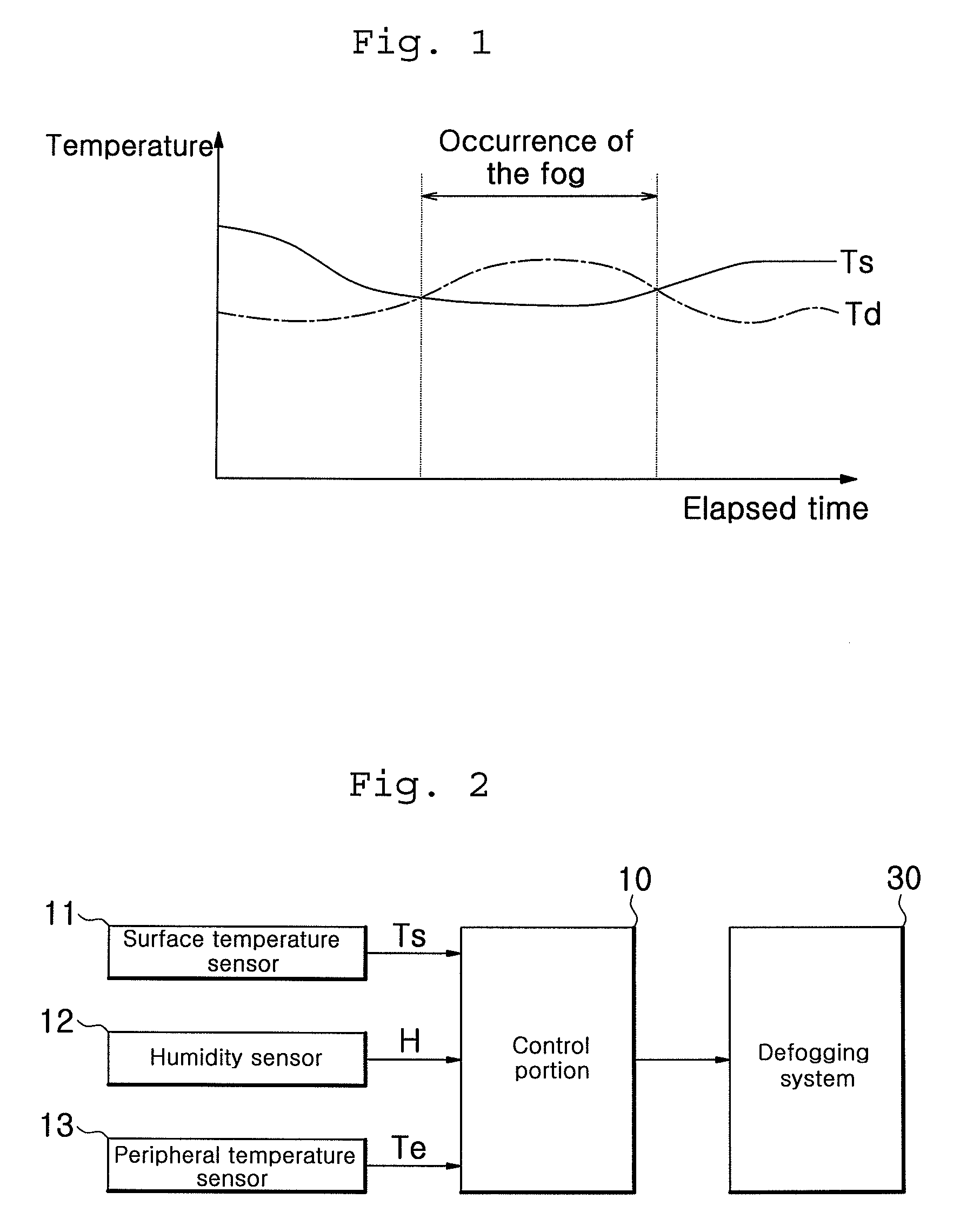
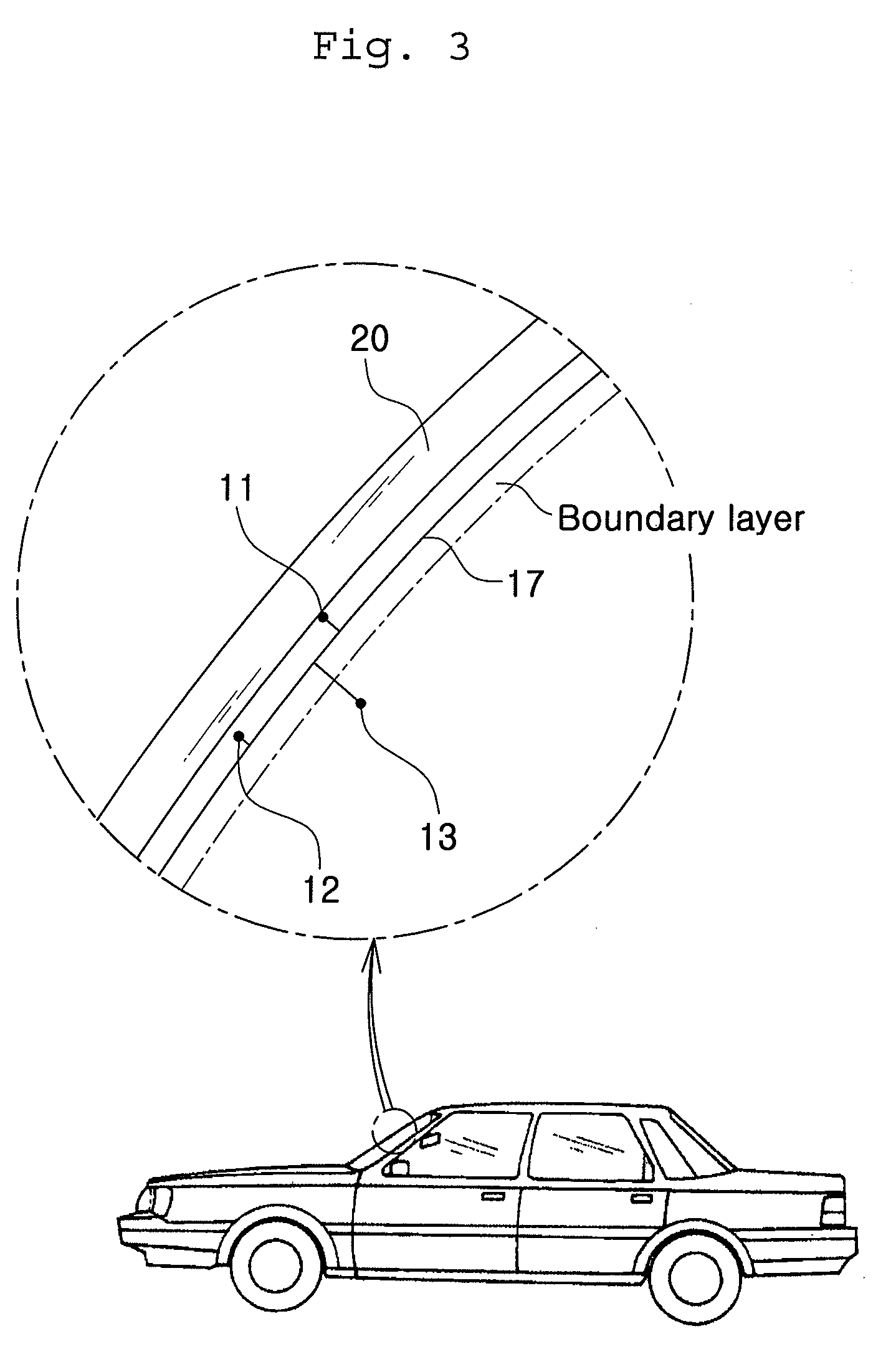
[0037] The automotive vehicle defogging of FIGS. 2-8 comprises a surface temperature sensor 11 mounted at a wind shield glass 20 of an automotive vehicle for detecting the surface temperature Ts of the glass, a humidity sensor 12 mounted at a position spaced from the wind shield glass 20 by a predetermined distance for detecting the humidity H around the wind shield glass 20, a peripheral temperature sensor 13 mounted biasedly at the inside from the wind shield glass 20 for detecting the peripheral temperature Te around the glass, and a control...


PUM


Abstract

An automotive vehicle defogging system prevents dissipation of energy required to defog the automotive vehicle wind shield. A surface temperature sensor mounted on the wind shield detects the glass surface temperature. A humidity sensor spaced from the wind shield glass by a predetermined distance detects the humidity around the wind shield. A peripheral temperature sensor mounted inside from the wind shield glass detects peripheral temperature around the glass. Dew point temperature is obtained in response to the detected humidity H and a temperature value based on the temperatures detected by the surface and peripheral temperature sensors. The presence of fog is detected by comparing the dew point temperature with the surface temperature Ts.

Description

BACKGROUND OF THE INVENTION [0001] 1. Field of the Invention [0002] The invention relates to a fogging detecting system for an automotive vehicle and a method for controlling the system, which is adapted to be able to secure the view of a driver by removing the fog formed on a wind shield glass of the automotive vehicle, more in particular, to a defogging system for an automotive vehicle and a method for controlling the same, which can prevent the excessive loss of power by expecting the time when the fog will occur approximately to the actual condition in consideration of the temperature distribution around the wind shield glass. [0003] 2. Background of the Related Art [0004] In general, a fogging phenomenon of forming dewdrops at the wind shield glass is produced when the humidity at the inside of the automotive vehicle is high and exterior temperature is low. In other words, as shown in FIG. 1, fog is produced when the surface temperature Ts of the wind shield glass is lower than...

Claims


Application Information

Patent Timeline
Patent Type & Authority Applications(United States)
IPC IPC(8): H05B1/02
CPCB60H1/00785H05B1/0236H05B2203/035H05B3/84B60S1/54
Inventor KIM, YOUNG-KILOH, SAE-WONLEE, JEONG-HOONYU, TAE-HWAN
Owner HANON SYST
Why Eureka
Try Eureka