Valve diaphragm with a compression restraining ring, and valve including same

Inactive Publication Date: 2006-12-28
WINCEK CHRISTOPHER P
View PDF27 Cites 24 Cited by
  • Summary
  • Abstract
  • Description
  • Claims
  • Application Information

AI Technical Summary

Benefits of technology

[0012] A valve is disclosed including a body, a bonnet, a flexible diaphragm adapted to be positioned between the bonnet and the body, and an actuator mechanism. The flexible diaphragm has a central portion and a peripheral portion surrounding the central portion, wherein the peripheral portion includes a substantially rigid ring extending continuously through or on the peripheral portion. The body has an input port, a central portion, and an output port. The actuator mechanism is operatively coupled to the diaphragm for moving the diaphragm between an open configuration wherein the input port and output port are in fluid communication with each other, and a closed configuration wherein the diaphragm blocks the central portion and prevents fluid flow between the input port and the output port. The bonnet is adapted to house the actuator mechanism, and the actuator mechanism is positioned in the bonnet.

Problems solved by technology

A major disadvantage with diaphragm valves is that the diaphragms wear out and require periodic replacement.
A problem arises in that the flexible diaphragm offers little resistance to forces exerted on the diaphragm as the fasteners are tightened.
During assembly of a diaphragm valve, there is a tendency to over-tighten the fasteners in an effort to assure leak-proof junctions.
Over-tightening of the fasteners causes over-compression of the diaphragm, which often results in rupture and early failure of the diaphragm.

Method used


Image

  • Valve diaphragm with a compression restraining ring, and valve including same
  • Valve diaphragm with a compression restraining ring, and valve including same
  • Valve diaphragm with a compression restraining ring, and valve including same

Examples


Embodiment Construction

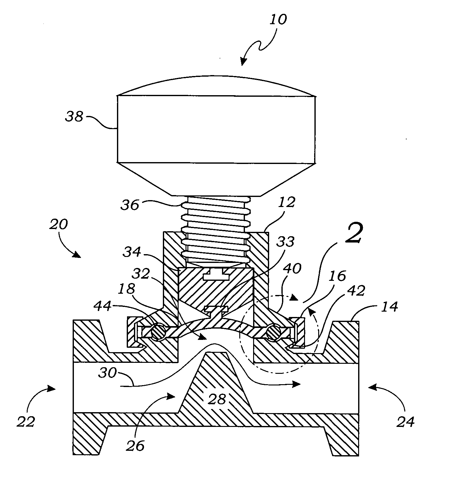
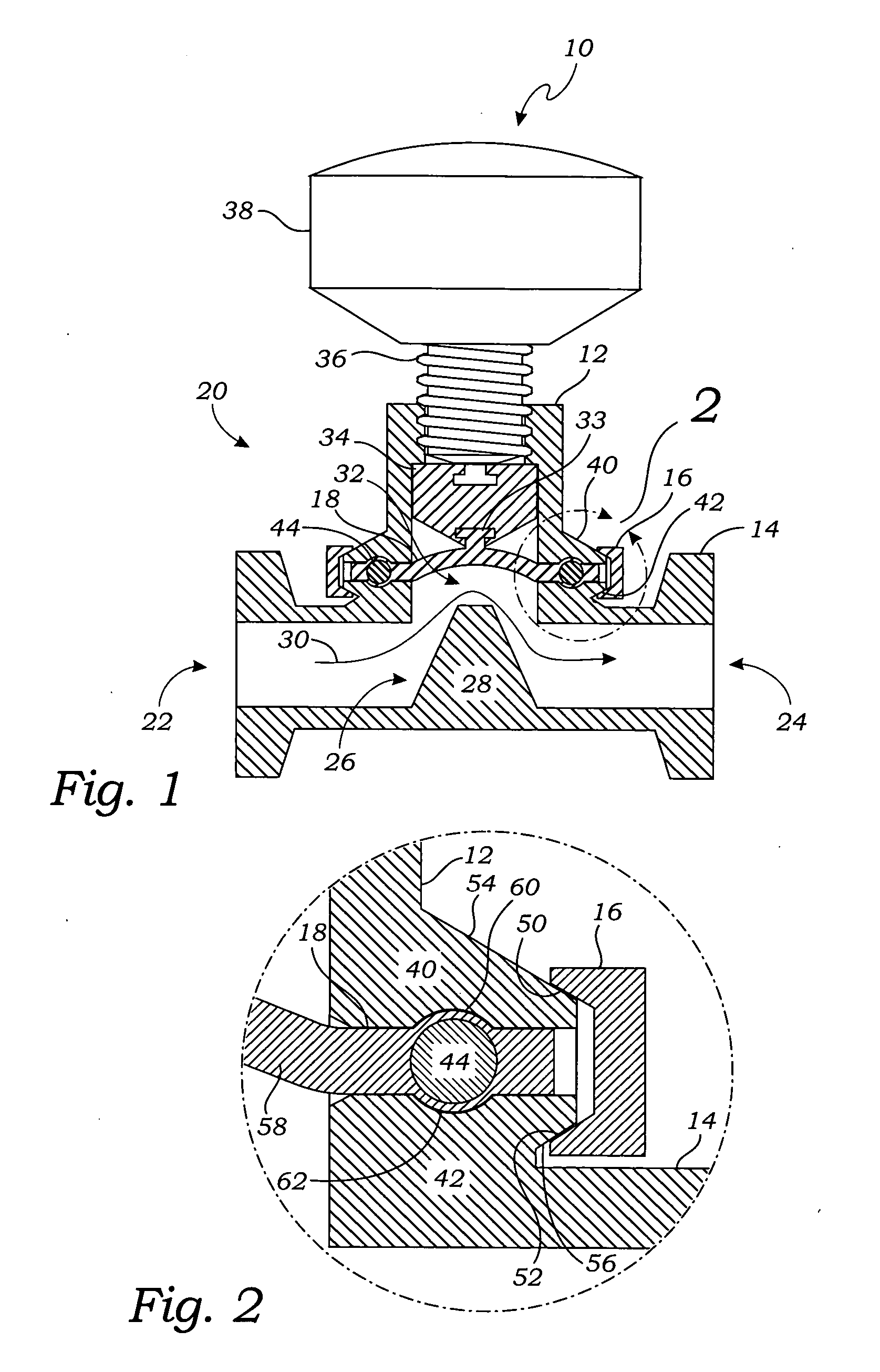
[0018]FIG. 1 is a perspective view of one embodiment of a valve 10 including a bonnet 12 clamped to a body 14 via a band clamp 16. A flexible diaphragm 18 is positioned between the bonnet 12 and the body 14. The flexible diaphragm 18 is moved between an open configuration, shown in FIG. 1, and a closed configuration, via an actuator mechanism 20 housed in the bonnet 12. The valve 10 of FIG. 1 is commonly referred to as a diaphragm valve.

[0019] In general, the body 14 has an input port 22, an output port 24, and a central portion 26 positioned between the input port 22 and the output port 24. In the open configuration of the diaphragm 18 of FIG. 1, the input port 22 and output port 24 are in fluid communication with each other. That is, fluid is free to flow between the input port 22 and output port 24 in the open configuration.

[0020] In the embodiment of FIG. 1, the valve 10 has a weir 28 in one side of a passageway 30 extending between input port 22 and the output port 24. The bo...


PUM


Abstract

A valve is disclosed including a body, a bonnet, a flexible diaphragm adapted to be positioned between the bonnet and the body, and an actuator mechanism. The flexible diaphragm has a central portion and a peripheral portion surrounding the central portion, wherein the peripheral portion includes a substantially rigid ring extending continuously through or on the peripheral portion. The body has an input port, a central portion, and an output port. The actuator mechanism is operatively coupled to the diaphragm for moving the diaphragm between an open configuration wherein the input port and output port are in fluid communication with each other, and a closed configuration wherein the diaphragm blocks the central portion and prevents fluid flow between the input port and the output port. The bonnet is adapted to house the actuator mechanism, and the actuator mechanism is positioned in the bonnet.

Description

CROSS-REFERENCE TO RELATED APPLICATIONS [0001] Not Applicable STATEMENT REGARDING FEDERALLY SPONSORED RESEARCH [0002] Not Applicable BACKGROUND OF THE INVENTION [0003] 1. Field of the Invention [0004] This invention relates generally to valves used to control flows of fluids, and more particularly to valves such as weir type diaphragm valves having moveable diaphragms to control flows. [0005] 2. Description of Related Art [0006] Diaphragm valves have moveable diaphragms to control fluid flows, and are commonly used for processing high purity fluids used in the pharmaceutical, biotechnical, chemical, food, and semiconductor industries. Their prevalent use is mainly due to their exceptional ability to resist damage from fluids (e.g., reactive chemicals). The diaphragms are typically the only moving parts that come in contact with the fluids, and the diaphragms typically isolate other moving parts from the fluids. [0007] A major disadvantage with diaphragm valves is that the diaphragms...

Claims


Application Information

Patent Timeline
IPC IPC(8): F16K1/00
CPCF16K7/126
Inventor WINCEK, CHRISTOPHER P.
Owner WINCEK CHRISTOPHER P
Why Eureka
Try Eureka