
Printed circuit card-based proximity sensor and associated method of detecting a proximity of an object

a technology of proximity sensor and printed circuit card, which is applied in the direction of transformer/inductance magnetic core, pulse technique, instruments, etc., can solve the problems of increasing the likelihood of sensor failure, changing the measured inductance of the sensor, and exceeding the tolerance of the sensor, so as to reduce failure, increase the reliability of the sensor, and reduce the cost

Active Publication Date: 2006-12-28
SIMMONDS PRECISION PRODS
View PDF14 Cites 2 Cited by
  • Summary
  • Abstract
  • Description
  • Claims
  • Application Information

AI Technical Summary

Benefits of technology

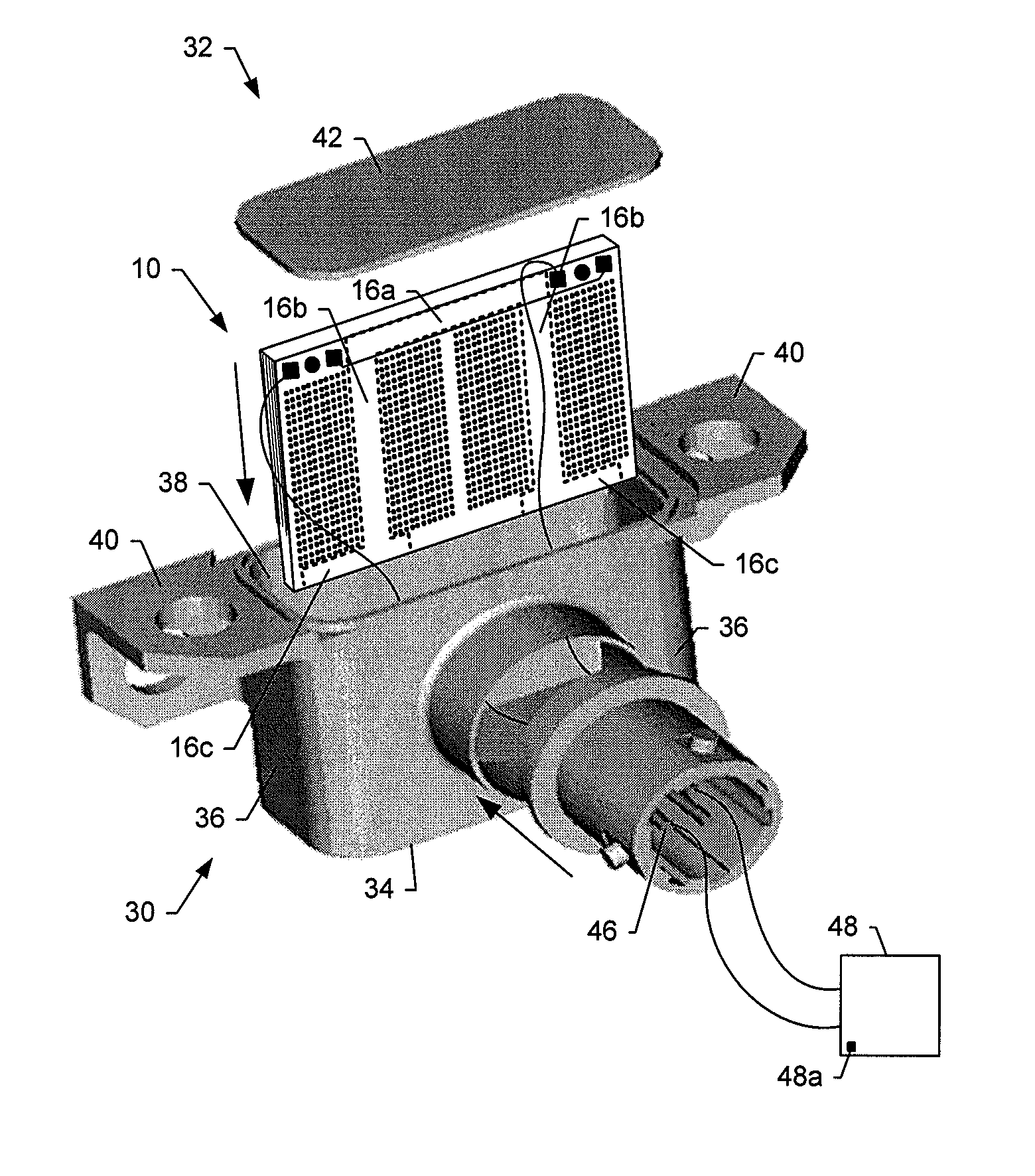
The present invention provides an improved proximity sensor and method of detecting the proximity of an object using a multilayer printed wiring board. The sensor includes a core and wound coils disposed about the core, which can detect the object based upon changes in the inductance of the coils. The sensor is cost-effective and operates with reduced failure under high-shock conditions. The sensor can be used as a variable-reluctance or eddy current loss sensor, and can be placed within a housing for added protection. The sensor can detect the object based upon the movement of the coils in relation to the magnetic field. The layers of the sensor are formed of a permeable material, and the coils are electrically driven to generate an alternating magnetic field. The sensor can be used in various applications, such as in a proximity sensor assembly for detecting the proximity of an object in an interior chamber of a housing.

Problems solved by technology

In many conventional proximity sensors, these bonds can be undesirably weak, thereby increasing the likelihood of sensor failure, particularly under high-shock conditions.
Movement of the bobbin relative to the core may result in a change in the measured inductance of the sensor, which in various instances can exceed required sensor tolerances.

Method used


Image

  • Printed circuit card-based proximity sensor and associated method of detecting a proximity of an object
  • Printed circuit card-based proximity sensor and associated method of detecting a proximity of an object
  • Printed circuit card-based proximity sensor and associated method of detecting a proximity of an object

Examples


Embodiment Construction

[0026] The present invention now will be described more fully hereinafter with reference to the accompanying drawings, in which preferred embodiments of the invention are shown. This invention may, however, be embodied in many different forms and should not be construed as limited to the embodiments set forth herein; rather, these embodiments are provided so that this disclosure will be thorough and complete, and will fully convey the scope of the invention to those skilled in the art. Like numbers refer to like elements throughout.

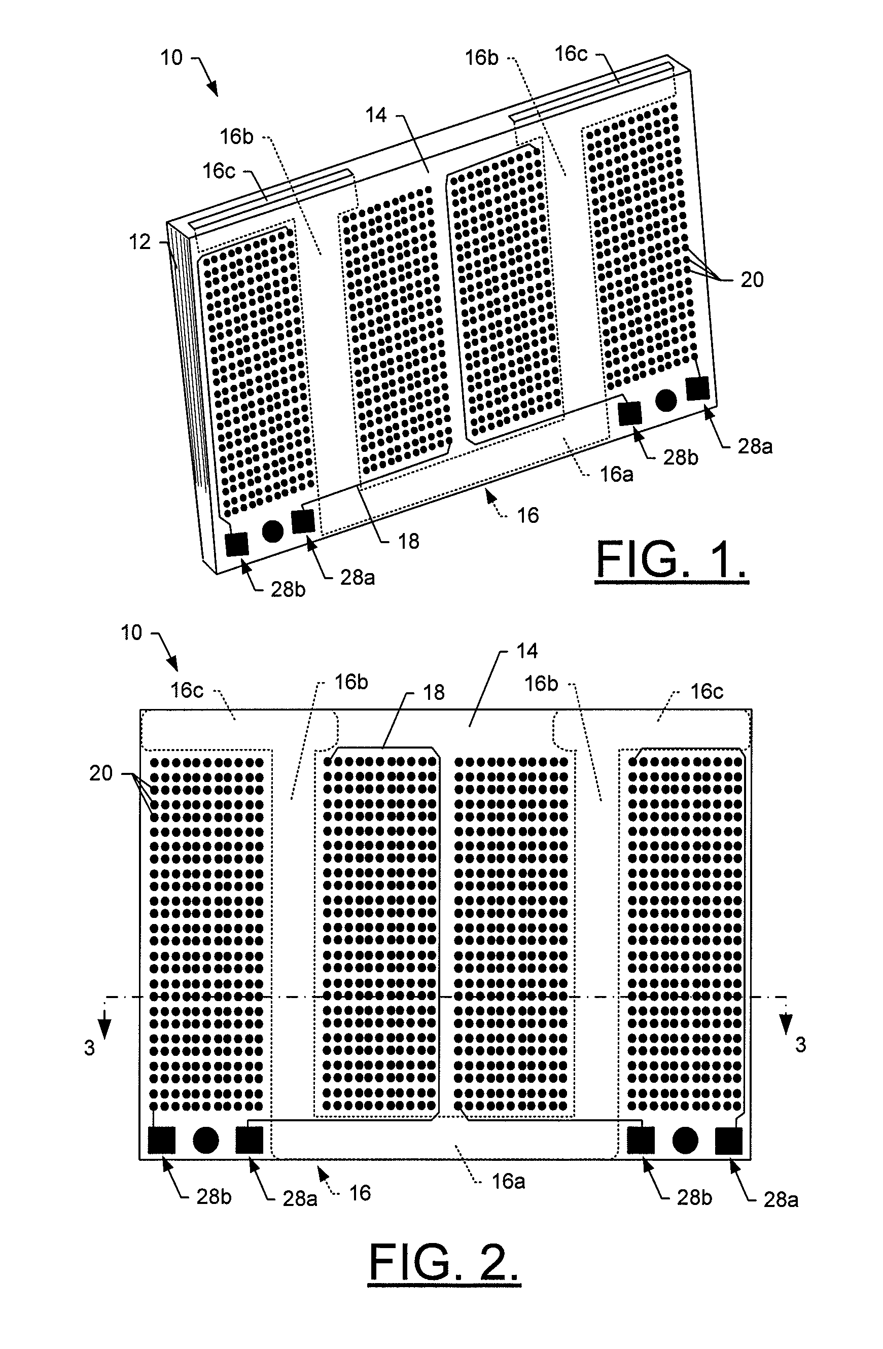
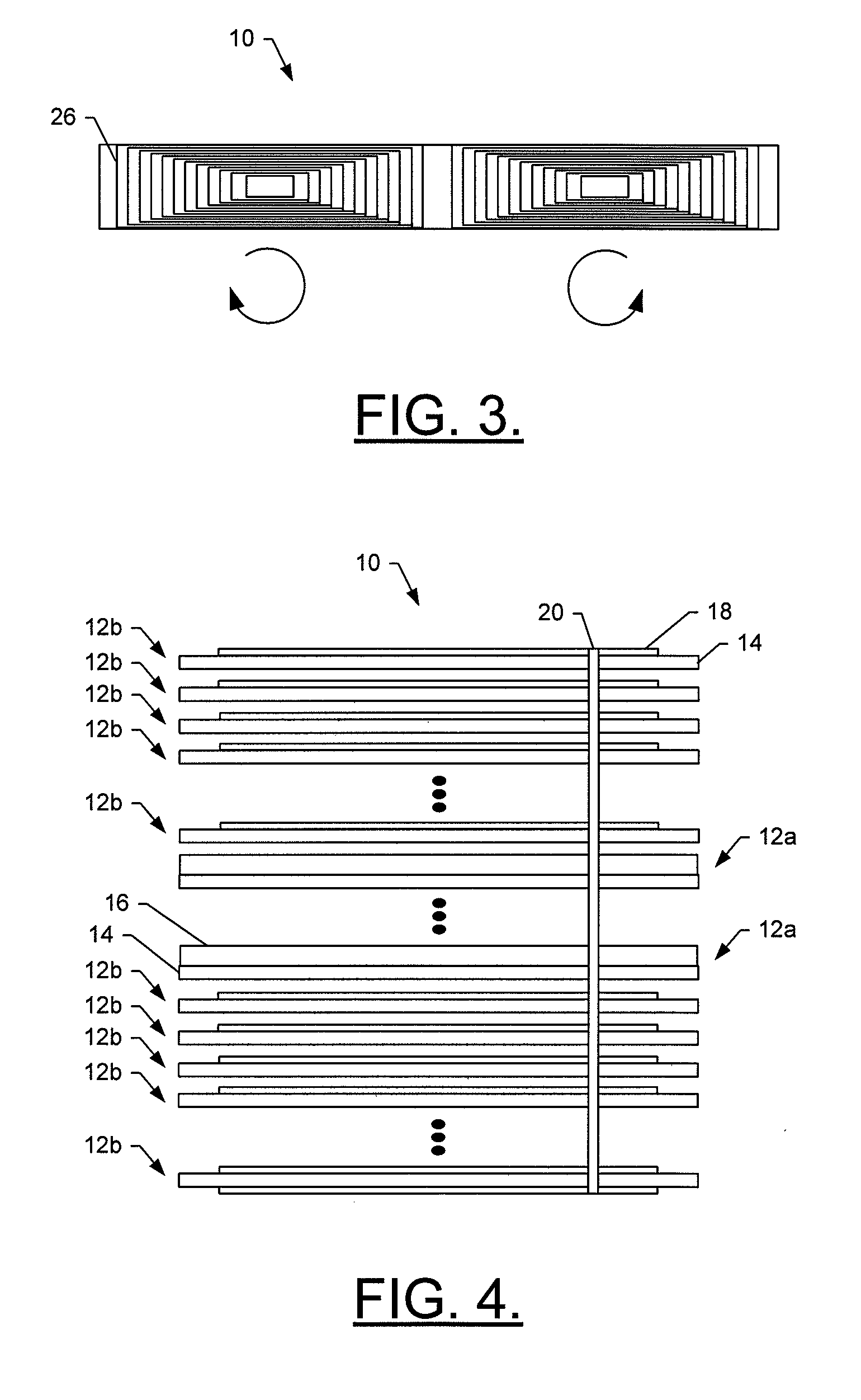
[0027] Reference is now made to FIGS. 1, 2, 3 and 4, which illustrate a perspective view, a top view, a cross-section view and an exploded side view, respectively, of a printed circuit-card based proximity sensor 10, in accordance with one embodiment of the present invention. As shown, the proximity sensor comprises a PWB that includes a plurality of layers 12 stacked on top of one another. The layers of the multilayer PWB, then, can include at least one...


PUM

PropertyMeasurementUnit
widthaaaaaaaaaa
lengthaaaaaaaaaa
lengthaaaaaaaaaa

Abstract

A proximity sensor assembly includes a multilayer printed wiring board proximity sensor, the proximity sensor being operable as either a variable-reluctance sensor or an eddy current loss sensor. The proximity sensor includes a plurality of layers configured to form at least one wound coil disposed about at least a portion of a core. The coils are electrically driven to generate an alternating magnetic field such that the inductance of the coils changes when a permeable or conductive object is moved in relation to the magnetic field. The change in inductance is recognized and used to detect the proximity and presence of an object relative to the sensor.

Description

CROSS-REFERENCE TO RELATED APPLICATIONS [0001] This application is a divisional of U.S. application Ser. No. 11 / 001,215, filed Dec. 1, 2004, which is hereby incorporated herein in its entirety by reference.FIELD OF THE INVENTION [0002] The present invention generally relates to inductive proximity sensors and, more particularly, to variable reluctance-type inductive proximity sensors and methods of detecting a proximity of an object. BACKGROUND OF THE INVENTION [0003] Proximity sensors have many different applications in many different industries. In the aerospace industry, for example, proximity sensors can be used within an aircraft to detect the position of various movable components. For example, proximity sensors can be used to detect the position of aircraft landing gear, landing gear doors, spoilers, passenger doors, and / or cargo doors. In this regard, such proximity sensors can be used to indicate aircraft conditions such as weight-on-wheels, landing gear up / down, doors open...

Claims


Application Information

Patent Timeline
Patent Type & Authority Applications(United States)
IPC IPC(8): G01B7/14
CPCG01B7/14G01V3/101Y10T29/49078Y10T29/49002Y10T29/49073H03K17/9505
Inventor LACLAIR, ROBERT DOWNINGMAIER, LAWRENCE CARLRINGER, ANTHONY DEAN
Owner SIMMONDS PRECISION PRODS
Learn More