Superconducting magnet apparatus for MRI

a magnet apparatus and superconducting technology, applied in the direction of superconducting magnets/coils, instruments, magnetic bodies, etc., can solve the problems of deteriorating mr image (magnetic resonance image), inability to resist a large electromagnetic force, and inducing mechanical oscillation, etc., to achieve high-quality mr image and reduce the effect of magnetic field oscillation

Inactive Publication Date: 2006-12-28
MITSUBISHI ELECTRIC CORP
View PDF3 Cites 25 Cited by
  • Summary
  • Abstract
  • Description
  • Claims
  • Application Information

AI Technical Summary

Benefits of technology

[0007] The invention was devised to solve these problems, and therefore has an object to obtain a high-quality MR image by preventing direct transmission of oscillation of the gradient coils to the superconducting magnets and reducing oscillation of the gradient coils while achieving a reduction of the overall superconducting magnet in size.
[0009] According to the invention, the bottom superconducting magnet is provided with the supporting member that supports the helium vessel of the bottom superconducting magnet connected integrally to the helium vessel of the top superconducting magnet via the connection portion. The supporting member is fixed to the vacuum vessel of the bottom superconducting magnet at one end, and is fixed to the floor surface in the vicinity of the end fixed to the vacuum vessel. This eliminates a supporting member to support the helium vessel from the vacuum vessel of the top superconducting magnet. Hence, oscillation of the gradient coil attached to the vacuum vessel is not directly transmitted to the helium vessel in the top superconducting magnet, and oscillation of the magnetic field can be reduced. It is thus possible to obtain a high-quality MR image.

Problems solved by technology

However, because the gradient coils are present between a pair of the annular superconducting magnets as described above and generate a pulsed magnetic field in a strong static magnetic field, they are susceptible to a large electromagnetic force and induce mechanical oscillation.
The oscillation is transmitted to the superconducting magnets, which causes a distance between a pair of the superconducting magnets to vary and thereby gives rise to minute magnetic field oscillation.
This results in a phenomenon that an MR image (Magnetic Resonance Image) is deteriorated.
However, because the need to provide a large frame to surround the superconducting magnets and the incapability of effectively fixing the outer peripheral portion of the gradient coils where the largest electromagnetic force is generated due to the structure for supporting the gradient coils only at the center, the open-type superconducting magnet apparatus for MRI in the related has a problem that oscillation and noise of the gradient coils are increased.

Method used


Image

  • Superconducting magnet apparatus for MRI
  • Superconducting magnet apparatus for MRI
  • Superconducting magnet apparatus for MRI

Examples


first embodiment

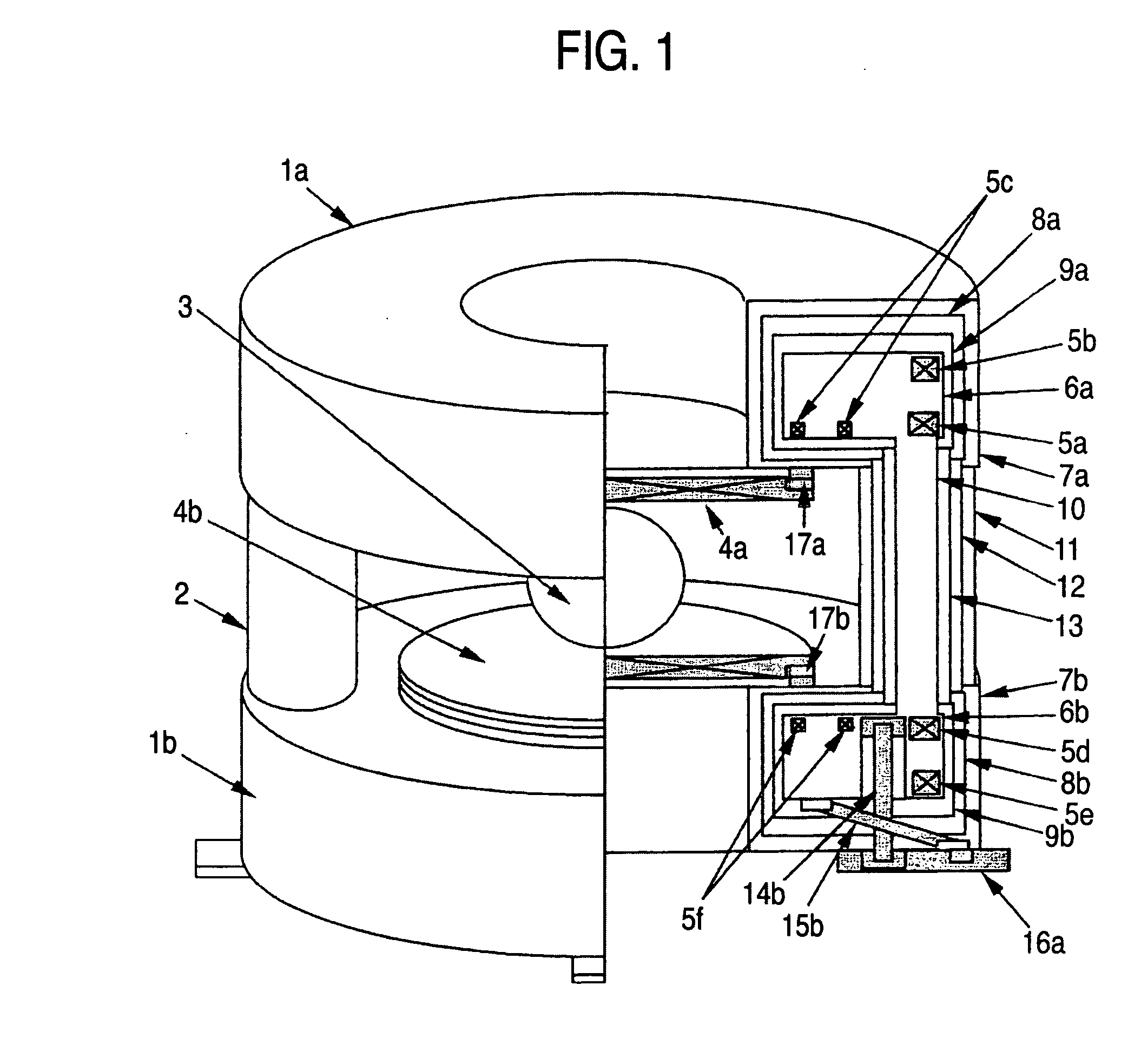
[0022] A first embodiment of the invention will now be described with reference to FIG. 1.

[0023] Referring to FIG. 1, alpha-numerals 1a and 1b denote, respectively, a top superconducting magnet and a bottom. superconducting magnet of an almost annular shape placed spaced apart one above the other, and numeral 2 denotes a connection portion that connects the top superconducting magnet 1a and the bottom superconducting magnet 1b. The top superconducting magnet 1a and the bottom superconducting magnet 1b make a pair and generate a highly homogeneous and stable static magnetic field 3 in a space at the center. Gradient coils 4a and 4b are attached, respectively, to the end faces on the center side of the top superconducting magnet 1a and the bottom superconducting magnet 1b, and they make a pair to generate a gradient magnetic field in the highly homogeneous static magnetic field space.

[0024] The internal structure of the top superconducting magnet 1a and the bottom superconducting ma...

second embodiment

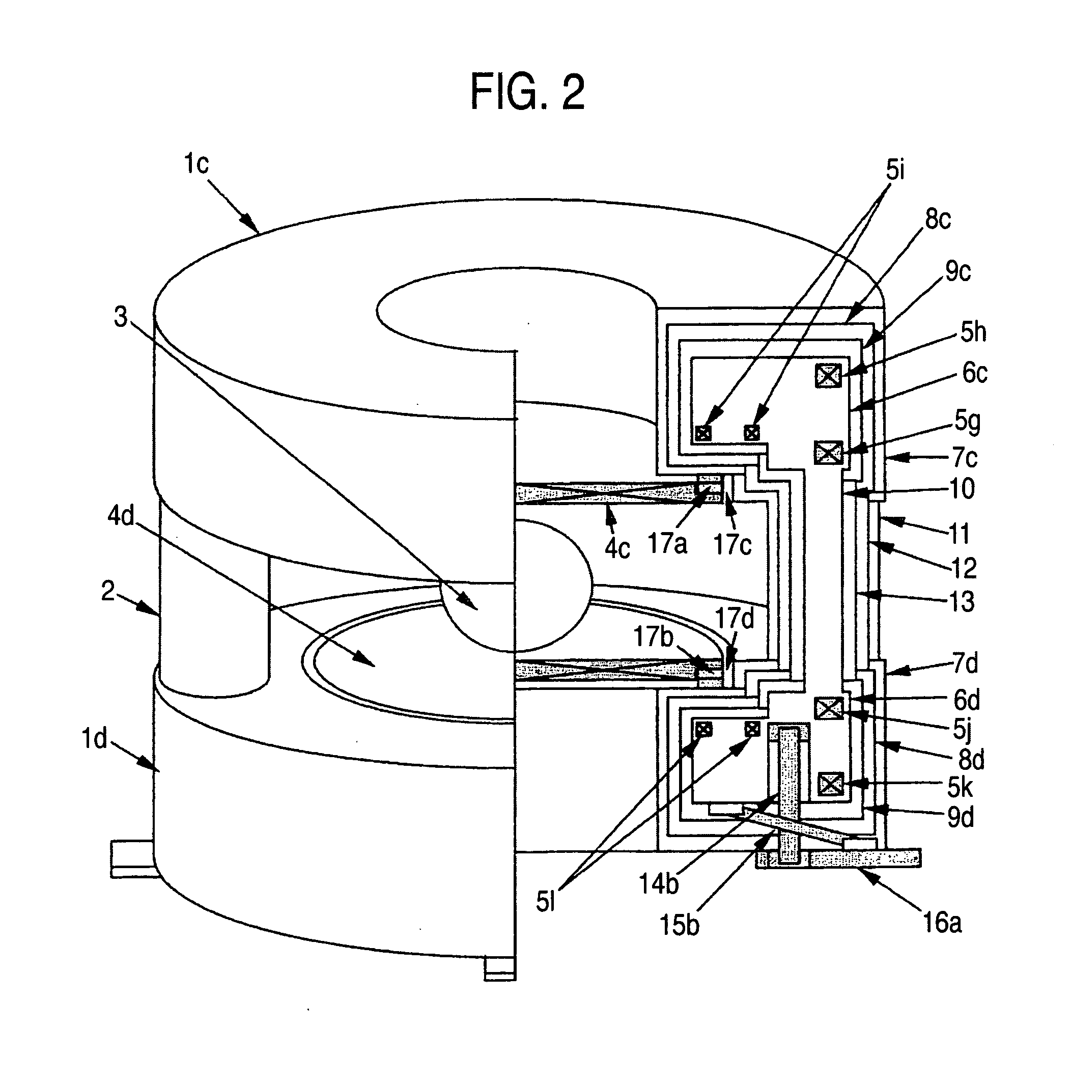
[0044] The gradient coils 4a and 4b are attached to flat planes on the inner end faces of the superconducting magnets 1a and 1b via the buffers 17 in the first embodiment above. However, the same advantages can be expected by providing concave portions 17c and 17d in the superconducting magnets 1a and 1b and disposing gradient coils 4c and 4d within the concave portions 17c and 17d as is shown in FIG. 2.

[0045] A second embodiment of the invention will now be described with reference to FIG. 2.

[0046] Referring to FIG. 2, alpha-numerals 1c and 1d denote a top superconducting magnet and a bottom superconducting magnet of an almost annular shape, and numeral 2 denotes a connection portion that connects the top superconducting magnet 1c and the bottom superconducting magnet id. The top superconducting magnet 1c and the bottom superconducting magnet 1d make a pair and generate a highly homogeneous and stable static magnetic field 3 in a space at the center. Gradient coils 4c and 4d are ...

third embodiment

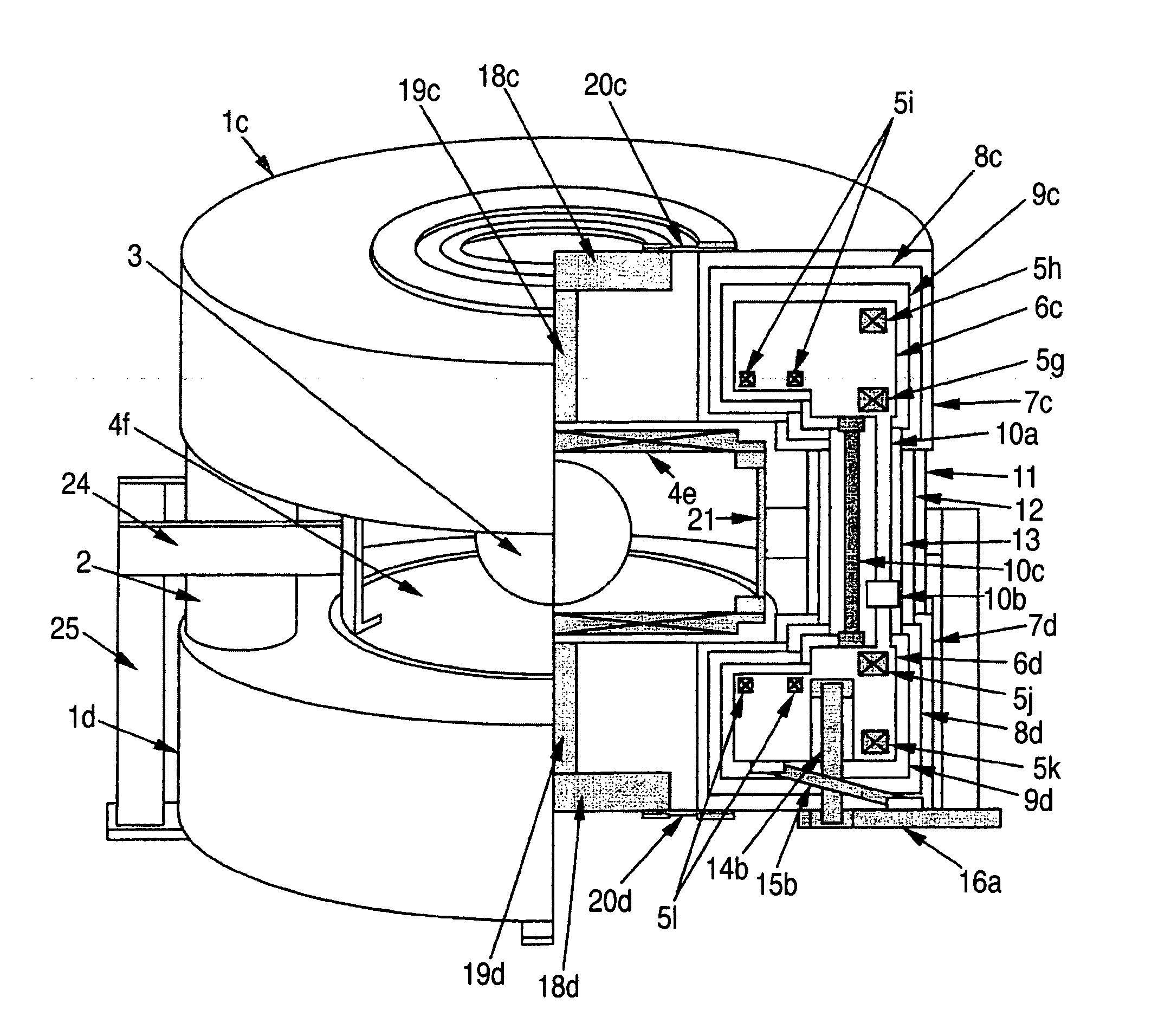
[0063] A third embodiment of the invention will now be described with reference to FIG. 3.

[0064] Referring to FIG. 3, alpha-numeral 18a denotes a mass body attached to a gradient coil 4c at the top nearly at the center via a connection member 19a using a hole at the center of the top superconducting magnet. Alpha-numeral 18b denotes a mass body attached to a gradient coil 4d at the bottom nearly at the center via a connection member 19b using a hole at the center of the bottom superconducting magnet. The mass of the mass bodies 18a and 18b is about 50 kg to 200 kg. A material of the mass bodies 18a and 18b is non-magnetic metal having a large specific gravity, for example, lead, stainless, or copper.

[0065] The other. portions are the same as or equivalent to those of the second embodiment.

[0066] In the third embodiment, the mass bodies 18a and 18b are attached to the gradient coils 4c and 4d nearly at the center. Hence, in comparison with a case in the absence of mass bodies, the...


PUM


Abstract

In a superconducting magnets for MRI configured to generate a homogeneous magnetic field and a gradient magnetic field in a space between a top superconducting magnet and a bottom superconducting magnet, the bottom superconducting magnet is provided with a supporting member that supports a helium vessel, and the supporting member is fixed to a vacuum vessel of the bottom superconducting magnet at one end, and is fixed to the floor surface in the vicinity of the end fixed to the vacuum vessel. A high-quality MR image can be thus obtained by preventing direct transmission of oscillation of the gradient coils to the superconducting magnet and reducing oscillation of the gradient coils while achieving a reduction of the overall superconducting magnet in size.

Description

BACKGROUND OF THE INVENTION [0001] 1. Field of the Invention [0002] The present invention relates to an apparatus used to obtain a satisfactory tomographic image by preventing fluctuation of a main magnetic field caused by oscillation of gradient coils in an open-type superconducting magnet for MRI (Magnetic Resonance Image Diagnostic Apparatus). [0003] 2. Description of Related Art [0004] In an open-type superconducting magnet for MRI in the related art as is disclosed, for example, in JP-A-2002-52004 (paragraph [0045] and FIG. 6), a frame is provided to surround an overall superconducting magnet comprising a top superconducting magnet and a bottom superconducting magnet placed one on the other, and supporting members are provided to penetrate through holes made at the centers of the top superconducting magnet and the bottom superconducting magnet. One end of the supporting member is fixed to the frame and the other end is attached to the central portion of the gradient coil for fi...

Claims


Application Information

Patent Timeline
Patent Type & Authority Applications(United States)
IPC IPC(8): G01V3/00
CPCG01R33/3815G01R33/3806
Inventor MATSUMOTO, TAKAHIRO
Owner MITSUBISHI ELECTRIC CORP
Why Eureka
Try Eureka