

Inkjet printer
a printer and inkjet technology, applied in the field of inkjet printers, can solve the problems of increased component cost, image deterioration, color unevenness, etc., and achieve the effect of preventing increased manufacturing costs, high quality image, and simple assembly work
- Summary
- Abstract
- Description
- Claims
- Application Information
AI Technical Summary
Benefits of technology
Problems solved by technology
Method used
Image

Examples
Embodiment Construction
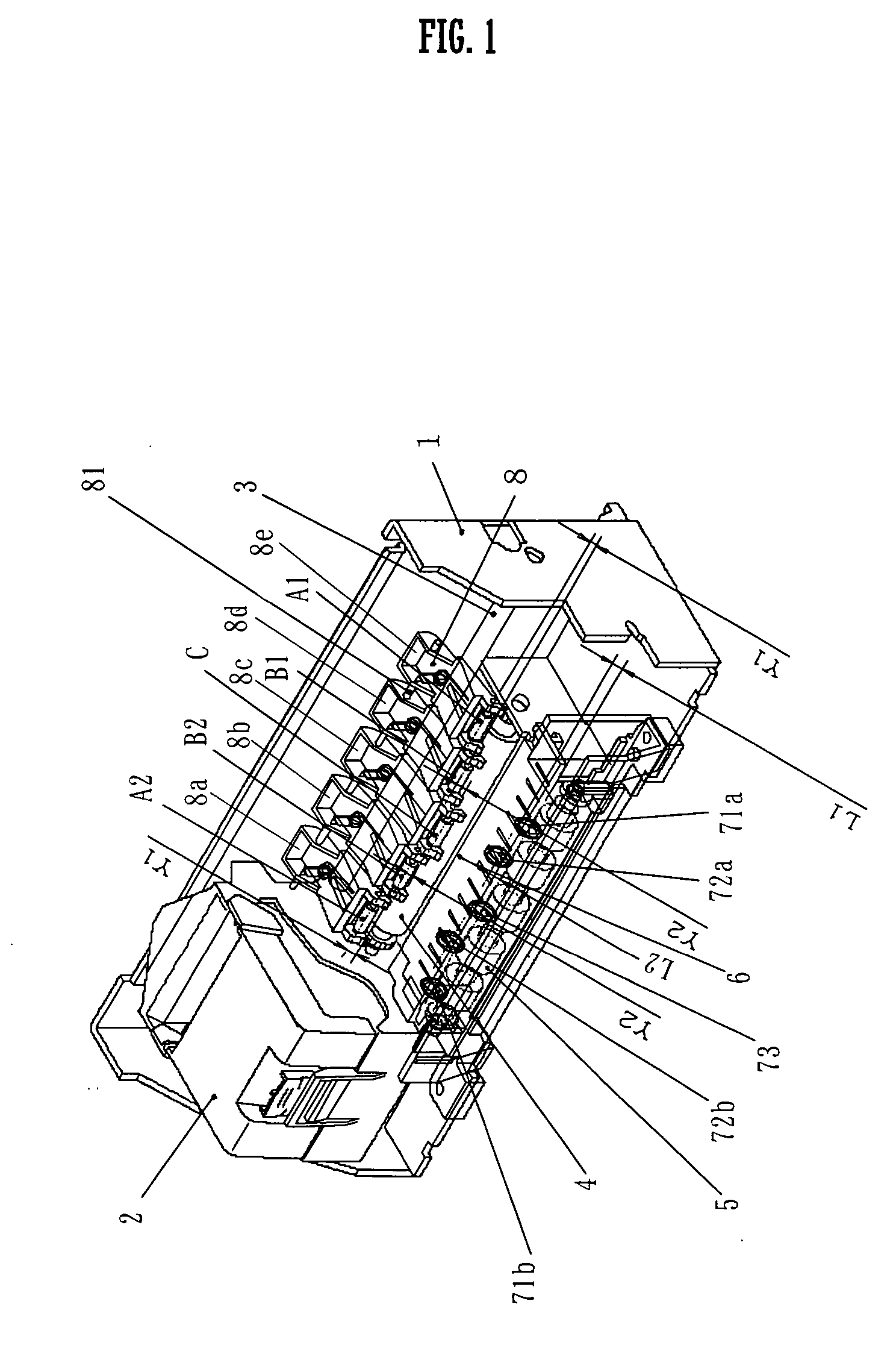
[0039]FIG. 1 is a perspective view of an inkjet printer according to an embodiment of the invention.
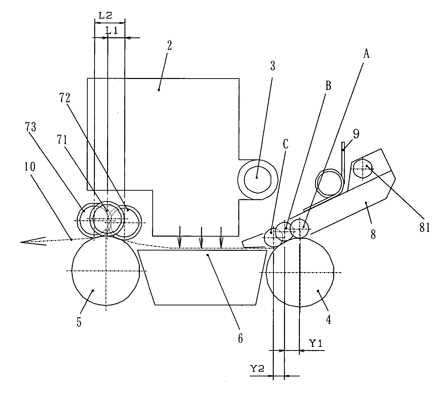
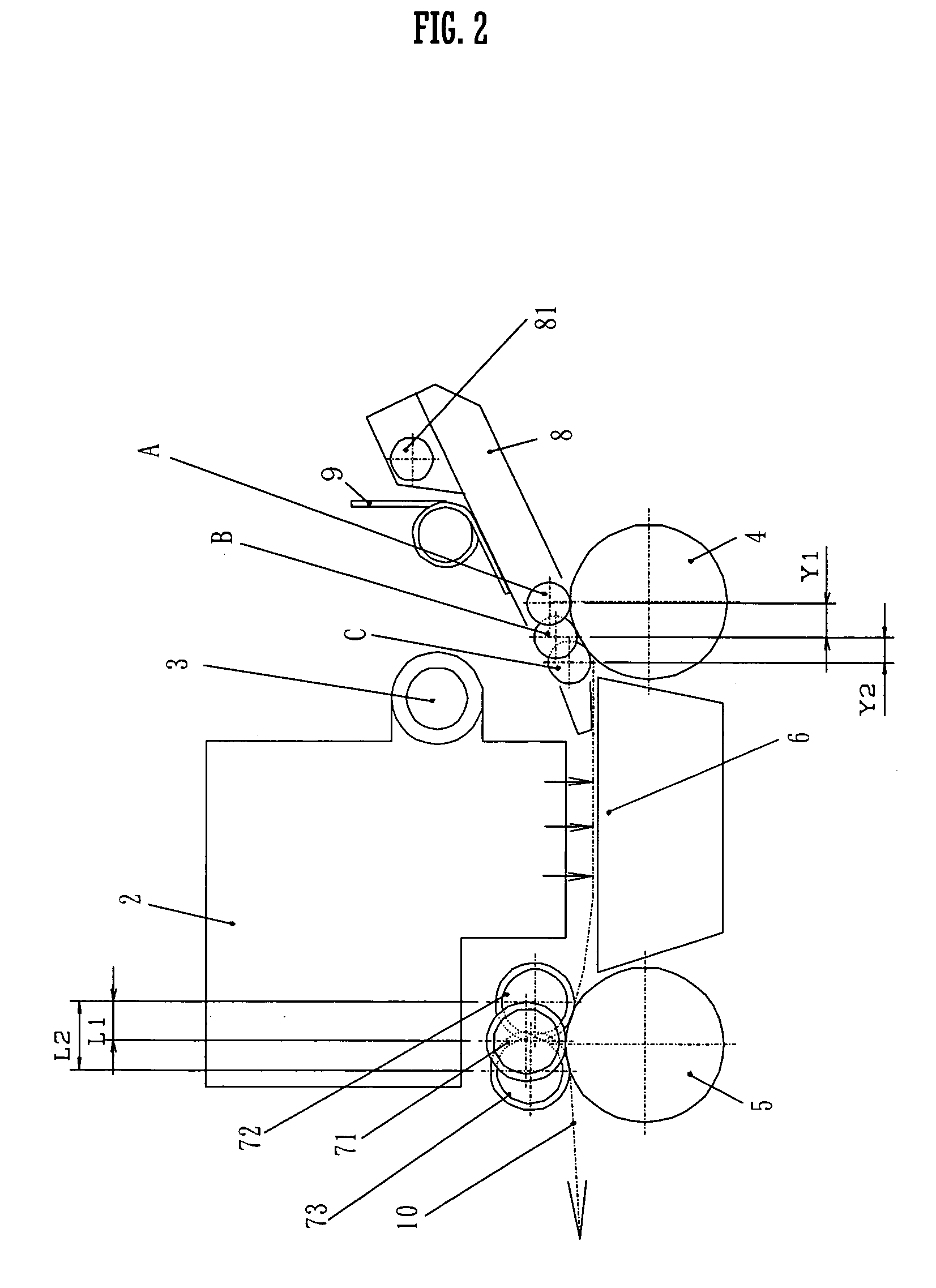
[0040]FIG. 2 is a schematic side view of relevant part of the inkjet printer. Referring to FIG. 2, a sheet 10 is fed leftward in the figure, i.e., in a slow scanning direction, by rotation of a not shown pick-up roller. The pick-up roller is driven by a driving motor and a set of driving gears, both not shown.
[0041] Then, the sheet 10 is nipped between a first transport roller 4 and first driven rollers A to C as pressed against the roller 4, and thereby transported by a predetermined distance downstream to an image forming area that is located below an inkjet print head 2. The inkjet print head 2 is held, and reciprocated in a fast scanning direction and an opposite fast scanning direction, by a carriage. The fast and opposite fast scanning directions are perpendicular to the slow scanning direction. During the reciprocation, the inkjet print head 2 ejects ink drops onto the sheet ...
PUM
 Abstract
Description
Claims
Application Information