Information Processing System for Producing Building Material, Building Material Production Method and Production Equipment, and Building Information Distribution System

a technology for information processing and building materials, applied in computer control, program control, instruments, etc., can solve the problems of reducing production efficiency, large space required for installation of production lines, and building costs, so as to improve production efficiency, reduce production efficiency, and improve production efficiency

Inactive Publication Date: 2008-03-13
HASHIMOTO SHINICHIRO +6
View PDF2 Cites 7 Cited by
  • Summary
  • Abstract
  • Description
  • Claims
  • Application Information

AI Technical Summary

Benefits of technology

[0020] According to an exemplary embodiment of the present invention, the specification and the quantity of the light gauge shape sheet steel are automatically determined from the design drawing information of a steel house, and based on them, a steel member order list is automatically output. Therefore, the material (steel member) totaling work required for producing the light gauge shape sheet steel which has conventionally been conducted manually may be eliminated, either fully or to the large extent. As a result, not only the transfer error is substantially eliminated, the whole work can be significantly simplified, and at the same time, the complicated desk work for ordering steel members may be reduced.
[0031] Also, according to the present invention, the shape of the shape steel is developed into a flat form, and the fastening hole position information is controlled one-dimensionally along the length of the members of each portion of the developed shape steel, so that the process of forming the fastening holes is easily controlled, thereby making it possible to secure the versatility of the data.

Problems solved by technology

One problem of a steel house is the building cost.
An increased number of fastening holes formed with the sheet steel kept stationary extremely reduces the production efficiency.
Also, in the case where the fastening holes are formed with the sheet steel kept stationary, a comparatively large waiting table for holding the sheet steel in standby state is required as a buffer, and therefore a large space is required to install the production line.
Further, the problem of a reduced overall production is posed depending on the productivity of the machine for forming the fastening holes.
However, the building materials are not produced using the CAD / CAM systems.
This, in turn, reduces the production efficiency of the building materials for a steel house.
The application field of this system disclosed in the publication is limited to the iron frame structure and the system is not applicable to the production of building materials from sheet steel having a thickness not less than 0.4 mm but less than 2.3 mm used for a low building.
Also, the configuration described in this publication is not a system for aiding the design and production by relating the CAD system to the CAM system.
In the prior art, therefore, the special member is unavoidably produced on a production line, for machining the special member, different from the production line for the general member and the application member.
In the conventional production control system for the light gauge shape sheet steel for a steel house, the productivity of the light gauge shape sheet steel for a steel house is generally reduced by the facts that (i) the work of opening the fastening holes for connecting the members is one factor reducing the productivity, (ii) the shape steel has different types including the general member, the application member and the special member, and especially the existence of “the special member” is a factor reducing the working efficiency of the conventional production equipment and the conventional production control system, (iii) the necessity of opening a multiplicity of fastening holes requires long time and a great amount of labor to fetch the information on the fastening holes such as the position, the shape and the machining accuracy of the fastening holes in the design stage, as the member control information for the production control system, and (iv) the information on the positions of the fastening holes to be formed are complicated.
Especially, the building information which may be stored in the form of paper media cannot be easily corrected.
(c) Conventionally, the building information are not very helpful to both the party providing them and the party using them, and therefore are not extensively used by other companies.
Nevertheless, companies generally do not construct a building by reusing the building information of another building constructed by another company.

Method used


Image

  • Information Processing System for Producing Building Material, Building Material Production Method and Production Equipment, and Building Information Distribution System
  • Information Processing System for Producing Building Material, Building Material Production Method and Production Equipment, and Building Information Distribution System
  • Information Processing System for Producing Building Material, Building Material Production Method and Production Equipment, and Building Information Distribution System

Examples


Embodiment Construction

[0065] Exemplary embodiments of the invention are explained below with reference to the drawings.

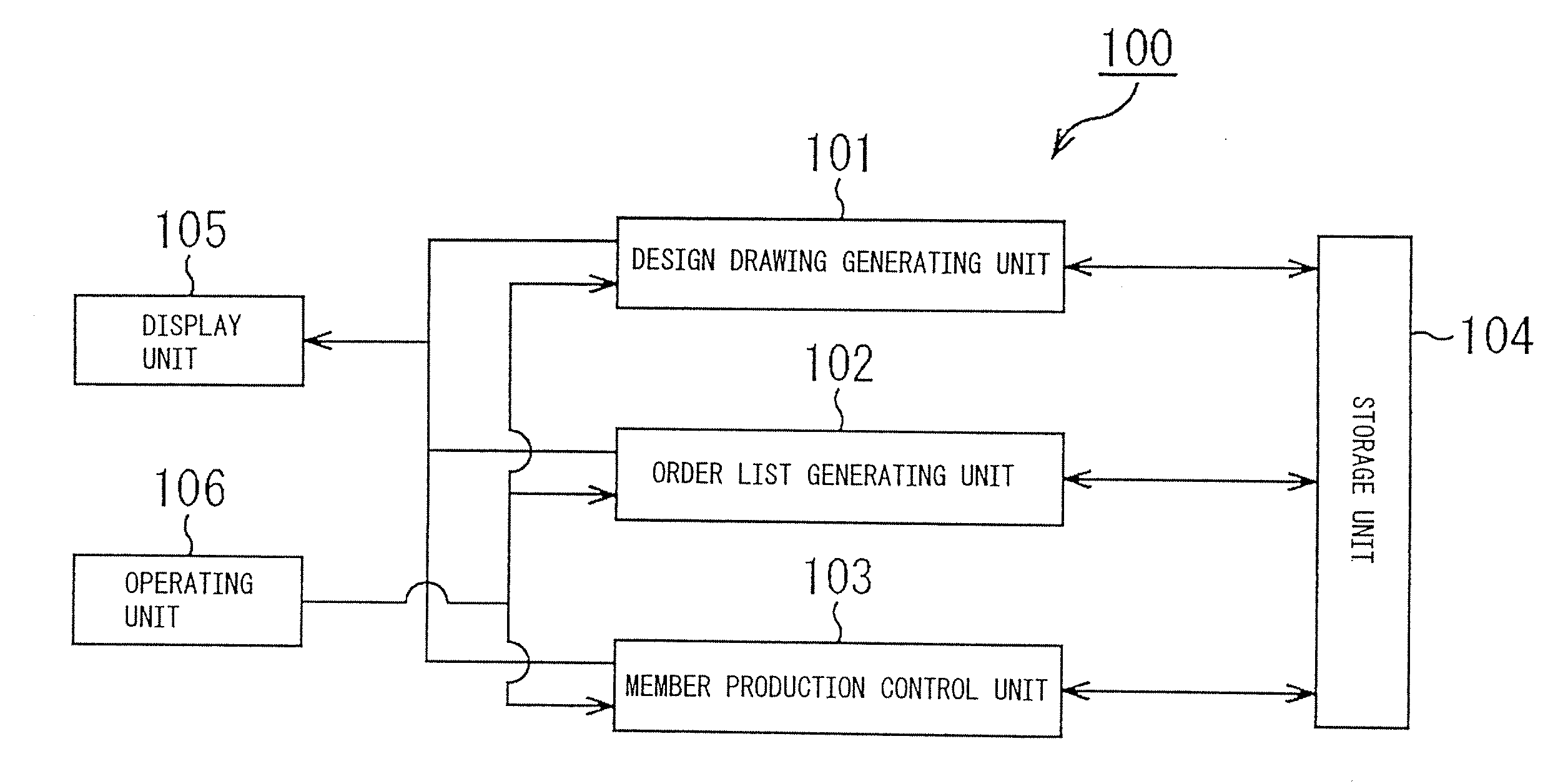
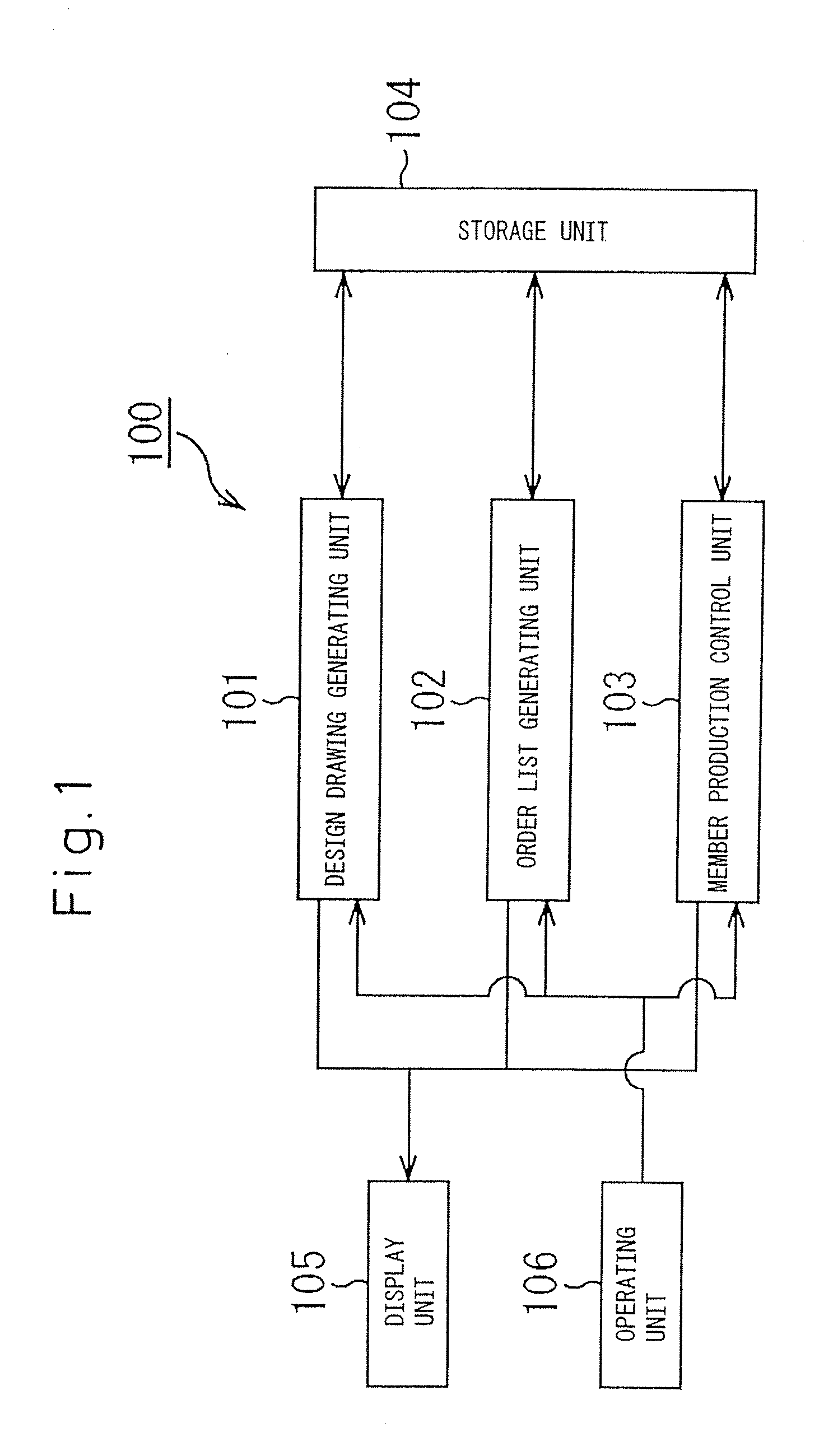
[0066] Referring to FIG. 1, an information processing system 100 according to an exemplary embodiment of the present invention can be used for efficiently producing the light gauge shape sheet steel for a steel house, and comprises a design drawing generating unit 101, an order list generating unit 102, a member production control unit 103, a storage unit 104, a display unit 105 and an operating unit 106.

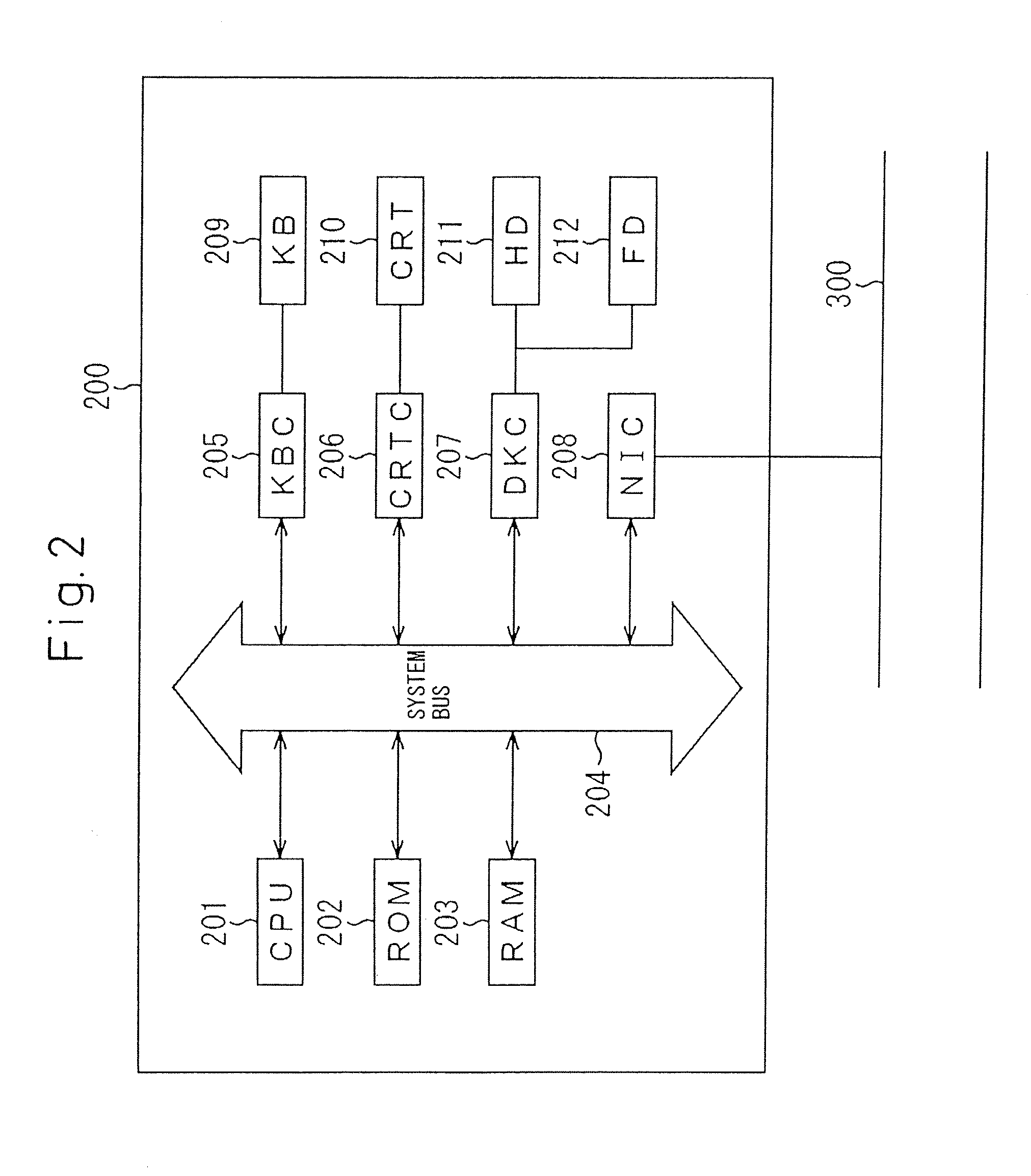
[0067]FIG. 2 shows a block diagram of a hardware configuration of the information processing system 100, the information processing system 100 can be implemented by, for example, a computer 200.

[0068] The computer 200, as shown in FIG. 2, comprises a CPU 201, a ROM 202, a RAM 203, a keyboard controller (KBC) 205 of a keyboard (KB) 209, a CRT controller (CRTC) 206 of a CRT display (CRT) 210, a disk controller (DKC) 207 for a hard disk (HD) 211 and a flexible disk (FD) 212, and a networ...


PUM

PropertyMeasurementUnit
thicknessaaaaaaaaaa
thicknessaaaaaaaaaa
workabilityaaaaaaaaaa

Abstract

An information processing system for producing a building material has a design drawing generator, a list generator and a member production controller. The design drawing generator generates design drawing information of an objective building. The list generator generates list information of the members used for the objective building. The member production controller controls the production of the members used for the objective building, based on the list information.

Description

CROSS-REFERENCE TO RELATED APPLICATION(S) [0001] This application is divisional of U.S. patent application Ser. No. 10 / 485,324 filed on Jul. 15, 2004 as a national stage application of PCT Application No. PCT / JP02 / 04857, which was filed on Jul. 26, 2002, and published on Feb. 13, 2003 as International Publication No. WO 03 / 012562 (the “International Application”). This application claims priority from the International Application pursuant to 35 U.S.C. §365. The present application also claims priority under 35 U.S.C. §119 from Japanese Patent Application Nos. 2001-227065 and 2001-314230, filed on Jul. 27, 2001 and Oct. 11, 2001, respectively, the entire disclosures of which are incorporated herein by reference.FIELD OF THE INVENTION [0002] The present invention relates to an information processing system, a building material production method and production equipment for producing a building material used for a steel house or, e.g., a panel formed by combining light gauge shape she...

Claims


Application Information

Patent Timeline
Patent Type & Authority Applications(United States)
IPC IPC(8): G06F19/00G05B19/4097G06F17/50G06Q30/00
CPCG05B19/4097G05B2219/32176G05B2219/35002G06F17/5004Y10T29/5136G06Q30/06Y10T29/49629Y10T29/5197G06F2217/04G06F30/13G06F2111/02Y10T83/9423Y10T83/944G06Q50/08
Inventor HASHIMOTO, SHINICHIROHIRAKAWA, TOMOHISASHIMIZU, JUNITO, YOSHITOMOIMAI, KIMIHIKOMURAHASHI, YOSHIMITSUHORIBE, TETSUSHI
Owner HASHIMOTO SHINICHIRO
Why Eureka
Try Eureka