Monitoring simulating device, method, and program

a monitoring device and simulating device technology, applied in the direction of program control, data switching network, instruments, etc., can solve the problems of affecting the reliability of the computer system, the failure of the monitoring device of the system, and the failure of the operation manager of the computer system to identify a failed piece of equipment, so as to reduce the workload of the designer, reduce the number of pieces of equipment to be monitored by the monitoring device of the system, and eliminate errors or omissions.

Inactive Publication Date: 2009-11-10
FUJITSU LTD
View PDF13 Cites 7 Cited by
  • Summary
  • Abstract
  • Description
  • Claims
  • Application Information

AI Technical Summary

Benefits of technology

[0014]The present invention aims to solve the problems that a designer of a computer system conventionally manually creates the above-described information table while referring to the network chart of the computer system, and the work of creating the information table is very complicated and the problem that there is a possibility of errors made by humans in setting error messages and provide a technique for automatically creating a complete list of failure points and error messages from the configuration information of a designed computer system.
[0018]With this configuration, if an error is detected during monitoring, a monitoring device can determine the urgency of the failure from the importance degree of the failure and notify an operations manager of the failure to take appropriate action. Also, a system designer can acquire information for design improvement to raise the reliability of a computer system.
[0019]In the present invention, monitoring simulation is performed by using a combination of the configuration information of a network system and a list of monitoring conditions for a system monitoring tool, information on the relationship between a failure point and a monitoring error message is collected, and creation of a complete list of failure points and error messages is automatically performed. This not only lightens the workload for a designer but also eliminates an error or omission caused by humans in setting error messages. Accordingly, it is possible to precisely identify a failure point from an error message. It is also possible to detect a point which is beyond of monitoring by doing a reverse lookup in a list obtained as the result of simulation and to detect a problem with monitoring such as an error message which can not identify a failure point.

Problems solved by technology

More specifically, in a computer system composed of a plurality of pieces of equipment, if a failure occurs in any of the pieces of equipment, error messages may be outputted in chain reaction not only from the failed piece of equipment but also from others which communicate with the failed piece of equipment.
For this reason, it is very difficult for an operations manager of a computer system to identify a failed piece of equipment only by looking at an error message.
However, especially in a networked computer system, the number of pieces of equipment to be monitored by a monitoring device of the system is usually excessively large, and the number of error messages is large as well.
That is very complicated work for a designer to associate a failure in a piece of equipment with a combination of error messages to be outputted while referring to a network chart.
Also, creating the information table manually may cause problems such as an omission in combinations of error messages and an increase in the possibility of errors in setting information identifying a failure point.
Therefore, conventional techniques are capable of quickly identifying the cause of a true error for a known error pattern but have difficulty in identifying the cause of a true error for an error pattern unregistered in an information table.

Method used


Image

  • Monitoring simulating device, method, and program
  • Monitoring simulating device, method, and program
  • Monitoring simulating device, method, and program

Examples


Embodiment Construction

[0032]An embodiment of the present invention will be described below using the drawings.

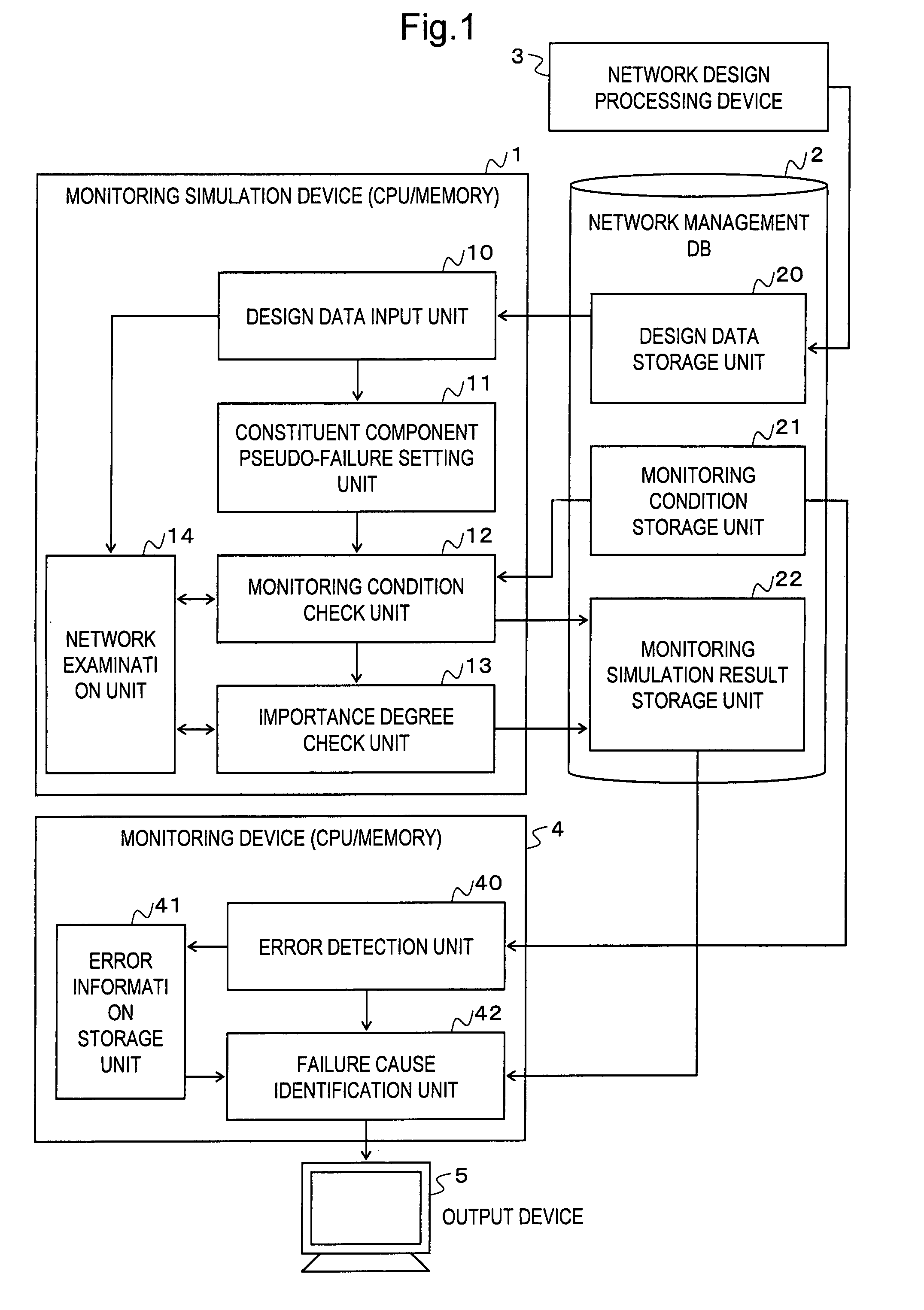
[0033]FIG. 1 is a diagram showing an example of the configuration of a monitoring simulation device according to the embodiment of the present invention. A monitoring simulation device 1 includes a design data input unit 10, a constituent component pseudo-failure setting unit 11, a monitoring condition check unit 12, an importance degree check unit 13, and a network examination unit 14. These units are realized by a computer composed of a CPU, memory and the like, and software programs. A network management DB (database) 2 is connected to the monitoring simulation device 1.

[0034]The network management DB 2 includes a design data storage unit 20, a monitoring condition storage unit 21, and a monitoring simulation result storage unit 22.

[0035]A network design processing device 3 is a computer which designs a network system using CAD and stores the design data of the network system in the design dat...


PUM


Abstract

A design data storage unit stores design data of constituent elements constituting a computer system to be monitored. A monitoring condition storage unit stores monitoring conditions of abnormal detection of the object to be monitored and error information to be outputted when the object meets particular monitoring conditions. A constituent component simulated failure setting unit causes the constituent elements in the design data to simulate failure one by one. A monitoring condition check unit checks if each monitoring condition is met when one constituent element is set in a failed state by instructing a network examining unit to examine the design data and extracts all the error information relevant to the met monitoring conditions. According to the results, information on the correspondence between the failed constituent elements and all extracted error information is stored in a monitoring simulation result storage unit.

Description

CROSS-REFERENCE TO RELATED APPLICATIONS[0001]This application claims priority of PCT International Application PCT / JP2005 / 007773 filed on Apr. 25, 2005, the contents of which are incorporated by reference herein.BACKGROUND OF THE INVENTION[0002]1. Field of the Invention[0003]The present invention relates to a monitoring simulating device, method, and program for performing simulation to acquire the relationship between a failure point and a monitoring error message by using the configuration information of a computer system and creating a complete list of failure points and error messages.[0004]2. Description of the Related Art[0005]It is required in the operation of a computer system, if a failure occurs, to detect a failure point as soon as possible and restore the failure point to normal. To this end, the process is used to incorporate a monitoring device into a network system and monitor the operating state of the system using a monitoring tool.[0006]There are available various ...

Claims


Application Information

Patent Timeline
Patent Type & Authority Patents(United States)
IPC IPC(8): G06F9/44G06F13/10G06F13/12G06F11/22G06F13/00H04L12/70
CPCH04L12/2602H04L43/00H04L41/06H04L41/145
Inventor OKADA, TOSHIROYAMAZAKI, TOSHIYAUEHARA, TAKAO
Owner FUJITSU LTD
Why Eureka
Try Eureka