Reaction vessel

a technology of reaction vessel and temperature control, which is applied in the direction of fluid controller, chemistry apparatus and processes, laboratory glassware, etc., can solve the problems of difficult complicated work necessary for causing the reaction, and the inability to control the temperature of the reaction vessel, so as to prevent the entry of bubbles into the first chamber of the reaction vessel

Inactive Publication Date: 2012-11-29
SEIKO EPSON CORP
View PDF5 Cites 6 Cited by
  • Summary
  • Abstract
  • Description
  • Claims
  • Application Information

AI Technical Summary

Benefits of technology

[0017]According to this structure, bubbles having entered the first area disposed relatively far from the opening can easily shift toward the second area disposed relatively close to the opening when the opening of the vessel chamber is o

Problems solved by technology

In this condition, these bubbles in some cases prevent adequate movement of a liquid drop of the reaction liquid, or produce unnecessary flow of oil within the reaction vessel in accordance with the shift of the bubbles, which may cause disorder of temperature control within the reaction vessel.
When the first liquid and the second liquid overflow fro

Method used


Image

  • Reaction vessel
  • Reaction vessel
  • Reaction vessel

Examples


first embodiment

1. Reaction Vessel of First Embodiment

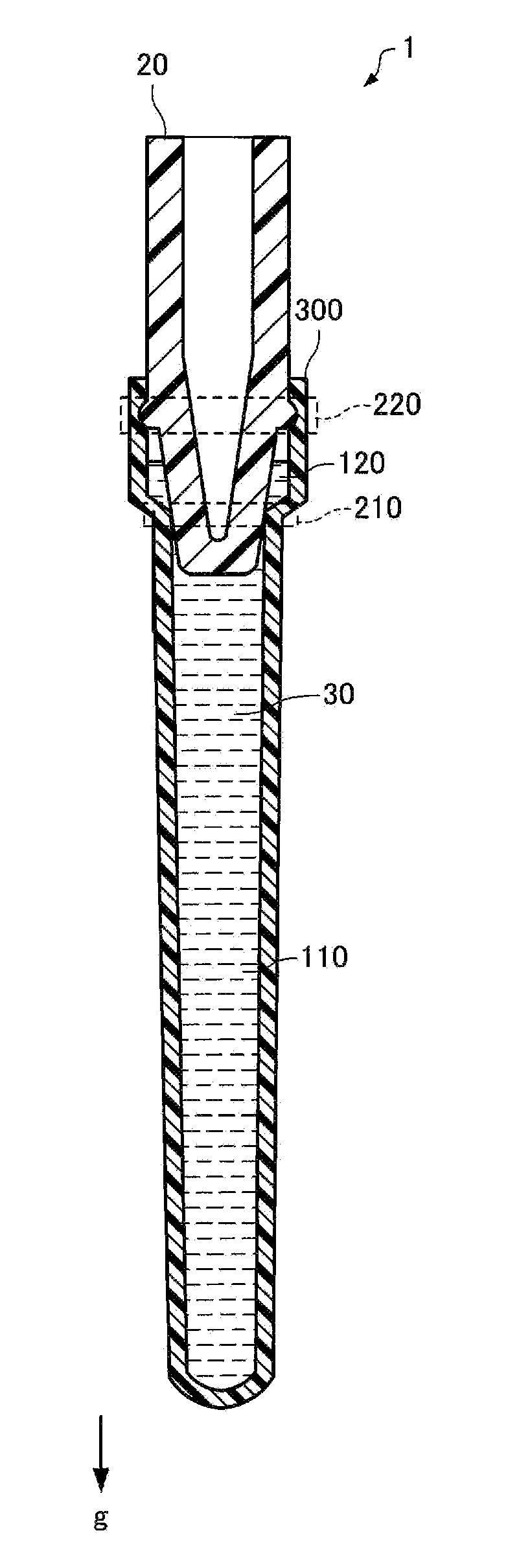
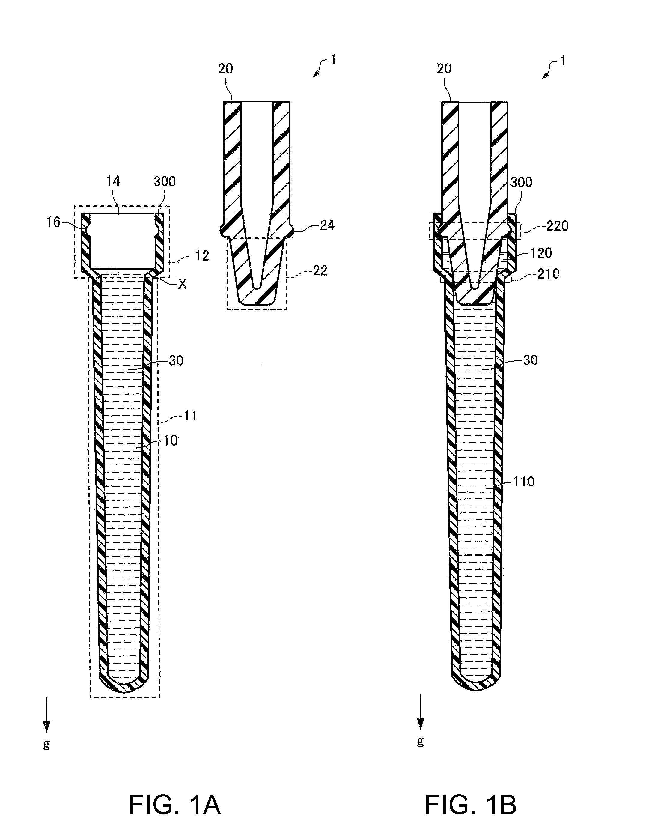
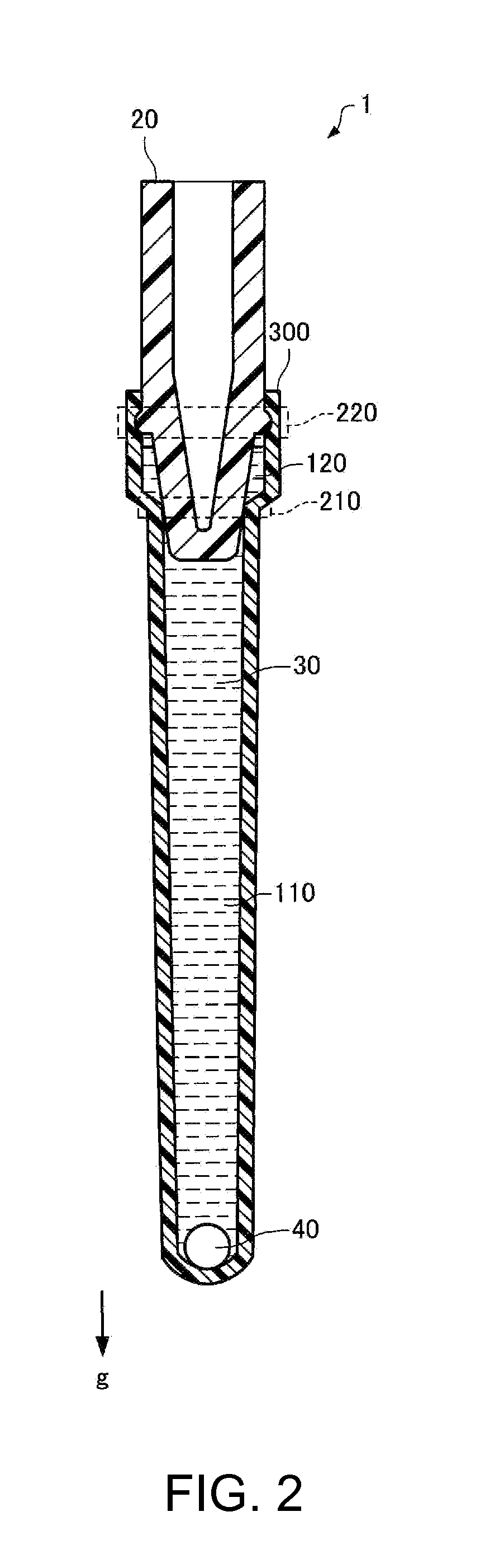
[0029]FIGS. 1A and 1B schematically illustrate a cross-sectional structure of a reaction vessel 1 according to a first embodiment. FIG. 1A shows a condition of the reaction vessel 1 whose cover 20 is removed from a vessel main body 300, while FIG. 1B shows a condition of the reaction vessel 1 whose cover 20 is attached to the vessel main body 300. FIG. 2 schematically illustrates a condition of the reaction vessel 1 into which a second liquid 40 is introduced. In each of FIGS. 1A, 1B, and 2, an arrow g indicates the direction of gravity.

[0030]The reaction vessel 1 according to the first embodiment includes a vessel chamber 10 having an opening 14, a first area 11, and a second area 12 to which the opening 14 is positioned closer than to the first area 11, a cover 20 which seals at least a part of the first area 11 to define a first chamber 110 and also seals at least a part of the second area 12 to define a second chamber 120, and a first liquid...

second embodiment

2. Reaction Vessel of Second Embodiment

[0052]FIGS. 3A and 3B schematically illustrate a cross-sectional structure of a reaction vessel 2 according to a second embodiment. FIG. 3A shows a condition of the reaction vessel 2 whose cover 20a is removed from a vessel main body 300a, while FIG. 3B shows a condition of the reaction vessel 2 whose cover 20a is attached to the vessel main body 300a. FIG. 4 schematically illustrates a condition of the reaction vessel 2 into which the second liquid 40 is introduced. In each of FIGS. 3A, 3B and 4, the arrow g indicates the direction of gravity. In this section, structures different from the corresponding structures of the reaction vessel 1 in the first embodiment are chiefly discussed. The components and parts in this embodiment corresponding to the components and parts of the reaction vessel 1 in the first embodiment have been given similar reference numbers, and the same detailed explanation is not repeated.

[0053]The reaction vessel 2 in the ...


PUM


Abstract

A reaction vessel which satisfies a relationship A<C+D<A+B on the assumption that the capacities of a first chamber and a second chamber are A and B, respectively, and that the volumes of a liquid stored in the first chamber and a liquid stored in the second chamber are C and D, respectively, so as to prevent entrance of bubbles into the reaction vessel.

Description

CROSS-REFERENCE[0001]This application claims priority to Japanese Patent Application No. 2011-114414, filed May 23, 2011, the entirety of which is hereby incorporated by reference.BACKGROUND[0002]1. Technical Field[0003]The present invention relates to a reaction vessel.[0004]2. Related Art[0005]Recently, with discovery of various genes relating to diseases and ailments, medical treatments utilizing genes such as genetic examinations and genetic therapies have been attracting attention. Moreover, a number of methods utilizing genes have been developed in the agricultural and stock-raising field for species distinction and species improvement, as expansion of technologies utilizing genes. For the purpose of utilizing genes, nucleic acid amplification techniques have been widely employed in these days. Typical known examples of the nucleic acid amplification techniques at present include a PCR (polymerase chain reaction) method. Today, the PCR method has become an essential and indisp...

Claims


Application Information

Patent Timeline
IPC IPC(8): B01J14/00
CPCB01L3/50825B01L7/525B01L2400/0457B01L2300/042B01L2200/0684
Inventor KOEDA, HIROSHI
Owner SEIKO EPSON CORP
Why Eureka
Try Eureka