

Communication device and communication method
a communication device and communication method technology, applied in the field of radio communication, can solve the problem of ineffective cancellation of interfering signals, reduce the interference of the own system on the other system, and reduce the degradation of the receiver performance of the own system
- Summary
- Abstract
- Description
- Claims
- Application Information
AI Technical Summary
Benefits of technology
Problems solved by technology
Method used
Image

Examples
first embodiment
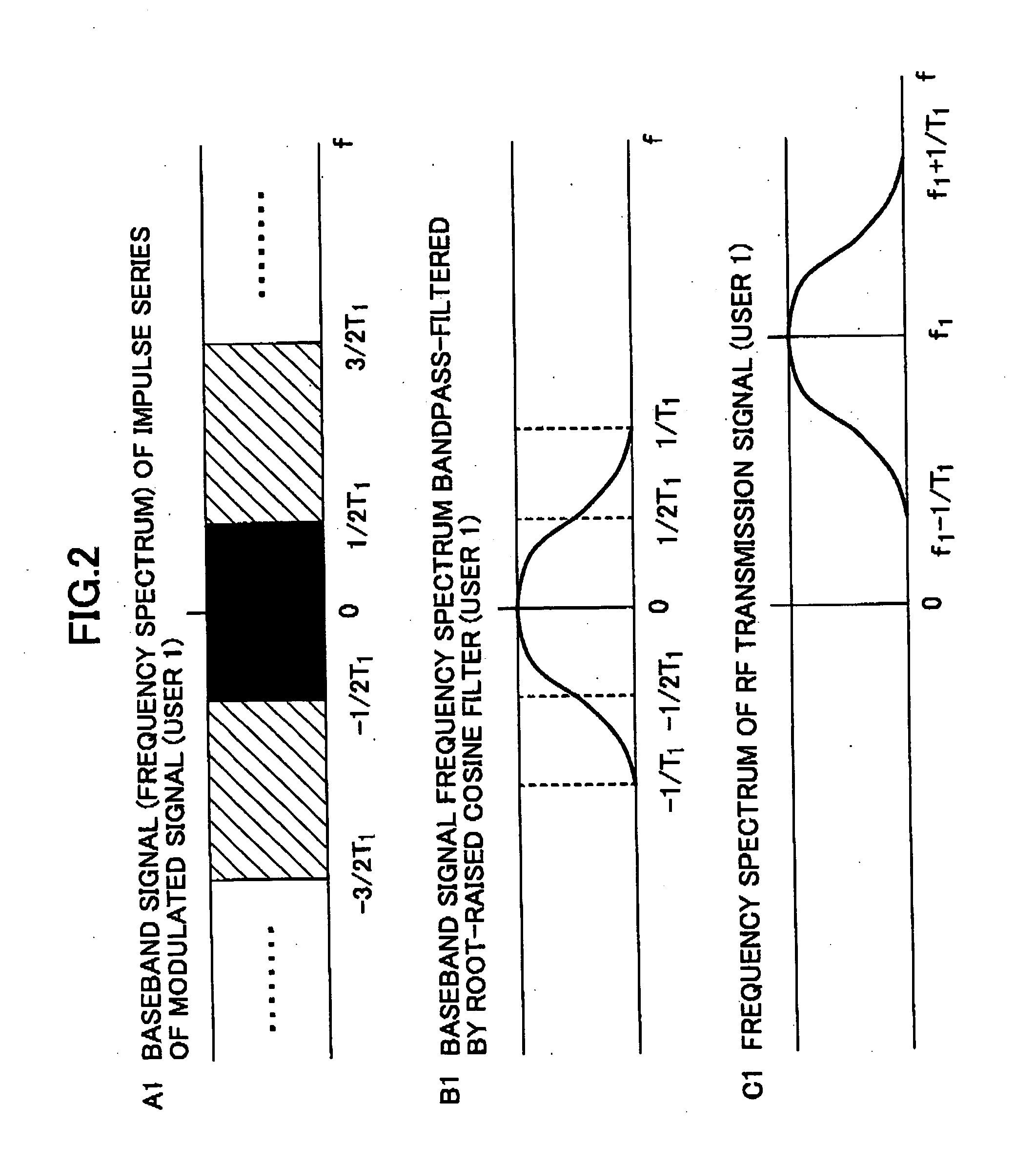
[0055]FIG. 8 shows a block diagram illustrating a transmitter according to an embodiment of the present invention. The transmitter 80 includes a transmission signal generator 81, a transmission shaping filter 82, a digital-to-analog (D / A) converter 83, an amplifier 85, an antenna 86, an interference condition detector 87 and a determiner 88. The transmission signal generator 81 generates a baseband transmission signal as shown in FIG. 2A. The transmission shaping filter 82 band-pass-filters the transmission signal. The transfer characteristics of this shaping filter 82 are properly set according to control information. The D / A converter 83 converts the baseband digital signal to an analog signal. The mixer 84 frequency-converts the analog signal with carrier frequency f1 of a desired signal. The amplifier 85 amplifies power of the frequency converted signal so as to transmit it from the antenna 86. The interference condition detector 87 detects parameters (such as frequency, power, ...
second embodiment
[0064] In a case where large interference occurs between the first and second systems when they simultaneously transmit signals, the transfer characteristics of the shaping filter 82 are properly adjusted. Signal band-pass-filtering is performed by the transmission shaping filter and a receiver shaping filter as a pair. Accordingly, a receiver shaping filter corresponding to the transmission shaping filter 82 is provided in the receiver side, not shown. The transfer characteristics of the receiver shaping filter can also be adjusted.
[0065] In the second embodiment, one example of adjustment of the transfer characteristics of the shaping filter is explained. In the explanation below, it is assumed that the center carrier frequencies of the desired system and the interfering system are measured, and their difference is large. It is also assumed that the transmission shaping filter 82 and the shaping receiver filter are root raised cosine filters that can modify their roll-off rates. ...
third embodiment
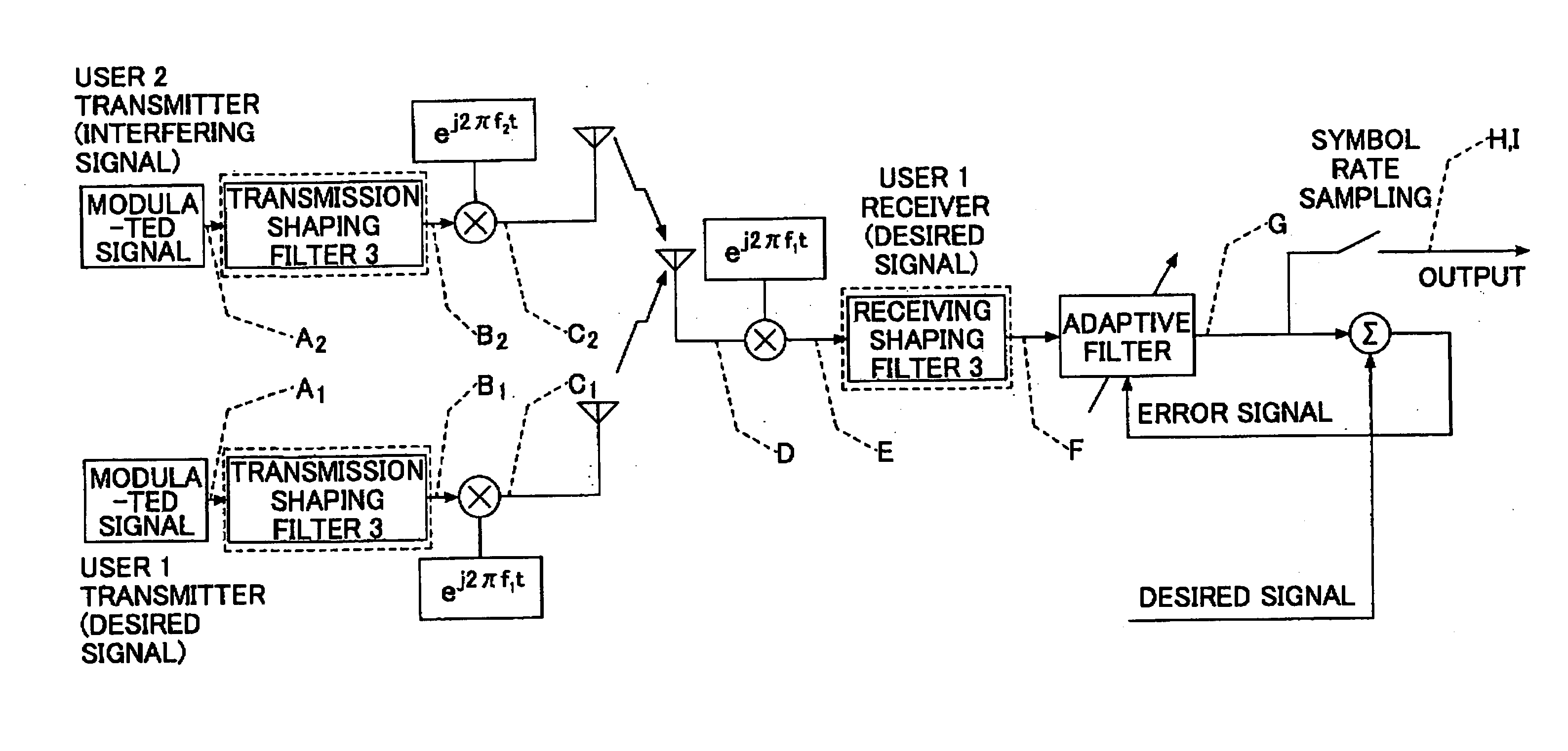
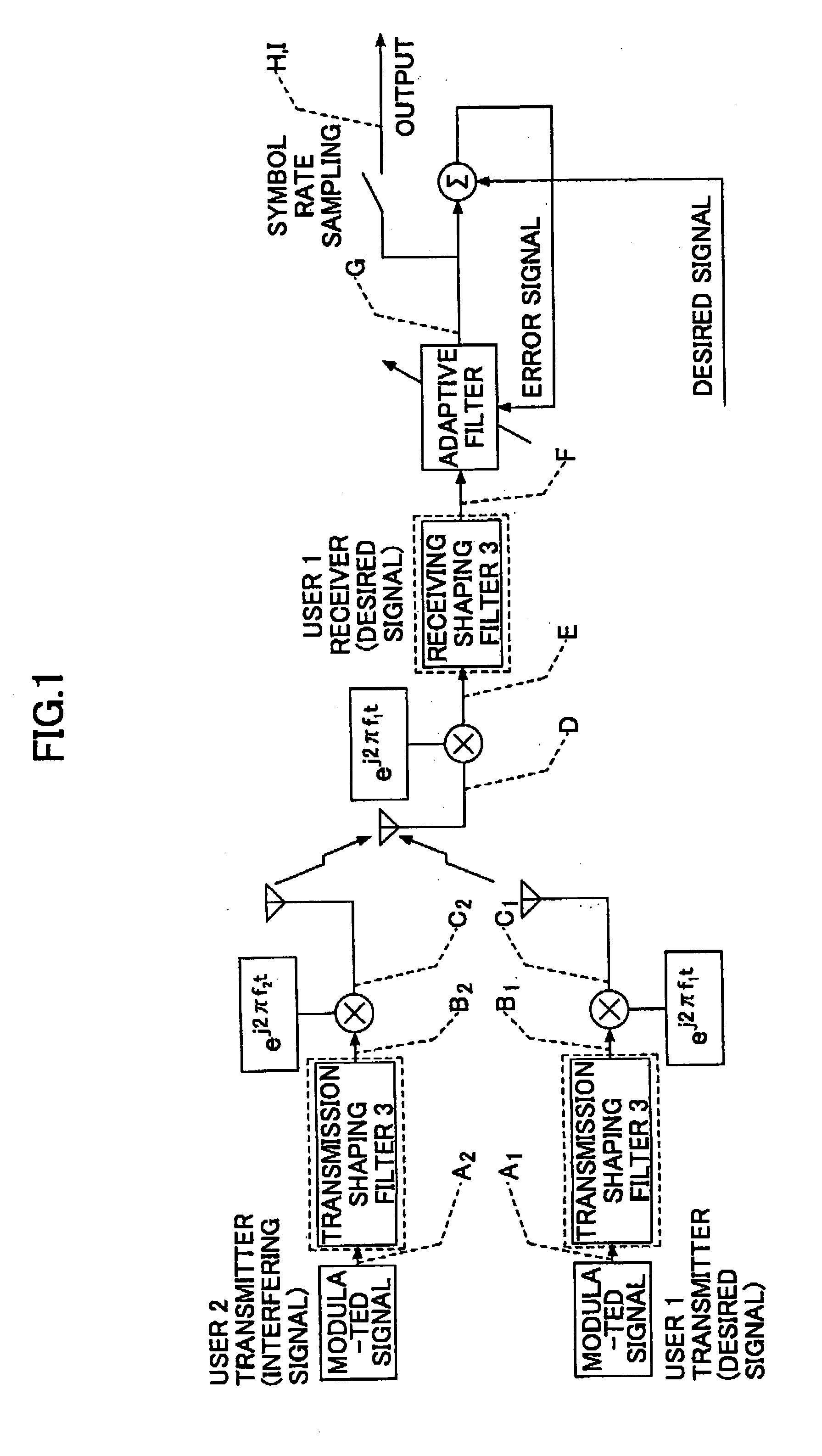
[0069] In a case where large interferences occur when the first and second systems simultaneously transmit in the same frequency band, the transfer characteristics of the shaping filter 82 is properly adjusted. Band-pass-filtering is performed by a pair of the transmission shaping filter and the receiver shaping filter. The transfer characteristics of the receiver shaping filter may also be adjusted. In this third embodiment, a frequency shift filter is used as an adaptive filter shown in FIG. 1 to cancel interference when the adjustment of the transfer characteristics of the transmission shaping filter and the receiver shaping filter is not enough to realize adequate cancellation reduction. In the explanation below, it is assumed that the difference (separation) between the central carrier frequencies of the desired and interfering systems is smaller than a predetermined value. The difference is measured at step 102 in FIG. 10. A frequency shift filter used in the receiver as an ad...
PUM
 Abstract
Description
Claims
Application Information