

Optical element for lateral light spreading in back-lit displays and system using same
a technology of optical elements and backlighting, applied in the field of optical lighting and displays, can solve the problems of affecting the illumination effect of the display, and the inability to achieve the desired illumination profil
- Summary
- Abstract
- Description
- Claims
- Application Information
AI Technical Summary
Benefits of technology
Problems solved by technology
Method used
Image

Examples
example 1
[0107] A structure was formed by laminating films of a multilayer polymer reflecting film, 3M Vikuiti™-brand ESR film, available from 3M Company, St. Paul, Minn., to both sides of a polycarbonate plate having a thickness of 3 mm using an optically clear pressure sensitive adhesive (PSA). The outer surfaces of the ESR film were then covered with strips of 3M Scotch™-brand Magic Tape. A pen laser, emitting polarized light having a wavelength of about 640 nm, was used to illuminate the structure at normal incidence to the ESR films. The size of the light beam incident on the structure was about 2 mm×3 mm.
[0108] At the output side of the structure, there was a dark central spot, corresponding to the forbidden angular region, that was elliptical in shape, having major and minor axes of 7 mm and 6 mm respectively. When a birefringent quartz plate was inserted into the laser beam with its optic axis placed at about 45° to the direction of polarization, the light pattern on the output side...
example 2
[0111] A film of ESR was laminated to one side of an acrylic plate, having a thickness of 3 mm, using an optically clear PSA, and the outer surface of the ESR was covered with strips of Magic Tape. The laser pen was used to illuminate the side of the laminate with the ESR film with a light beam 2 mm×3 mm. The resulting dark central spot on the output side of the laminate had dimensions of about 8 mm×9 mm.
[0112] The outer diameter of the output illumination pattern was not well defined, but was very large, at least 50 mm. This result is consistent with a higher value of θmax than in Example 1, since there was close matching between the refractive indices of the Magic Tape and the acrylic plate (n˜1.49 in each case).
example 3
[0113] A structure similar to that of Example 1 was constructed, except that the polycarbonate plate had a thickness of 12 mm. When normally illuminated by the pen light with an input beam of 2 mm×3 mm, the structure produced an oval output light pattern, about 26 mm×28 mm. The outer diameter of the light pattern, defined by θmax, was about 60 mm in diameter. The low intensity of the light at the outer edge of the pattern made it difficult to clearly discern the outer edge of the pattern.
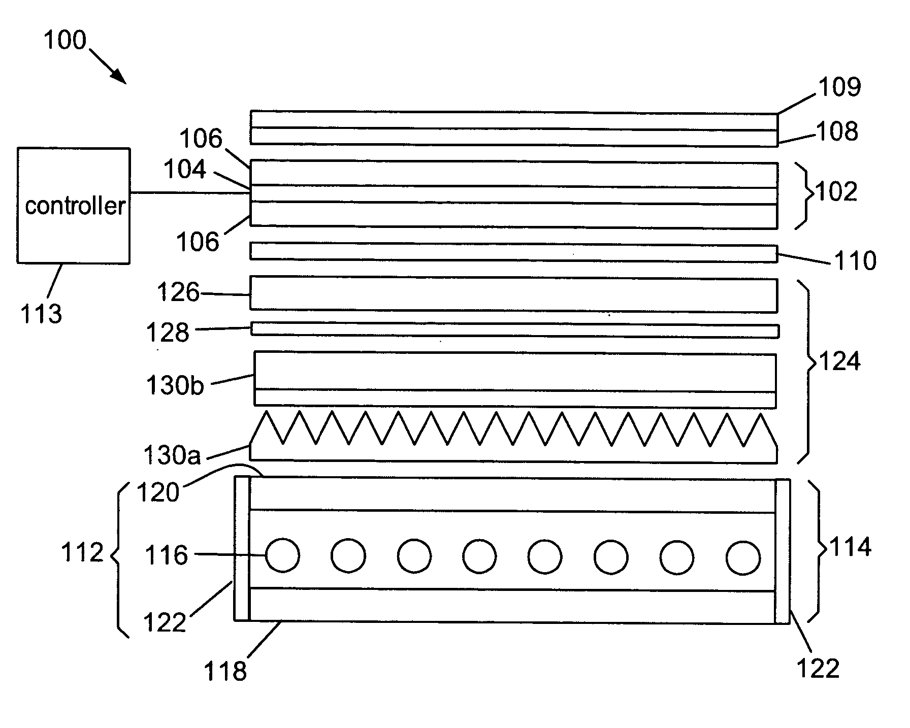
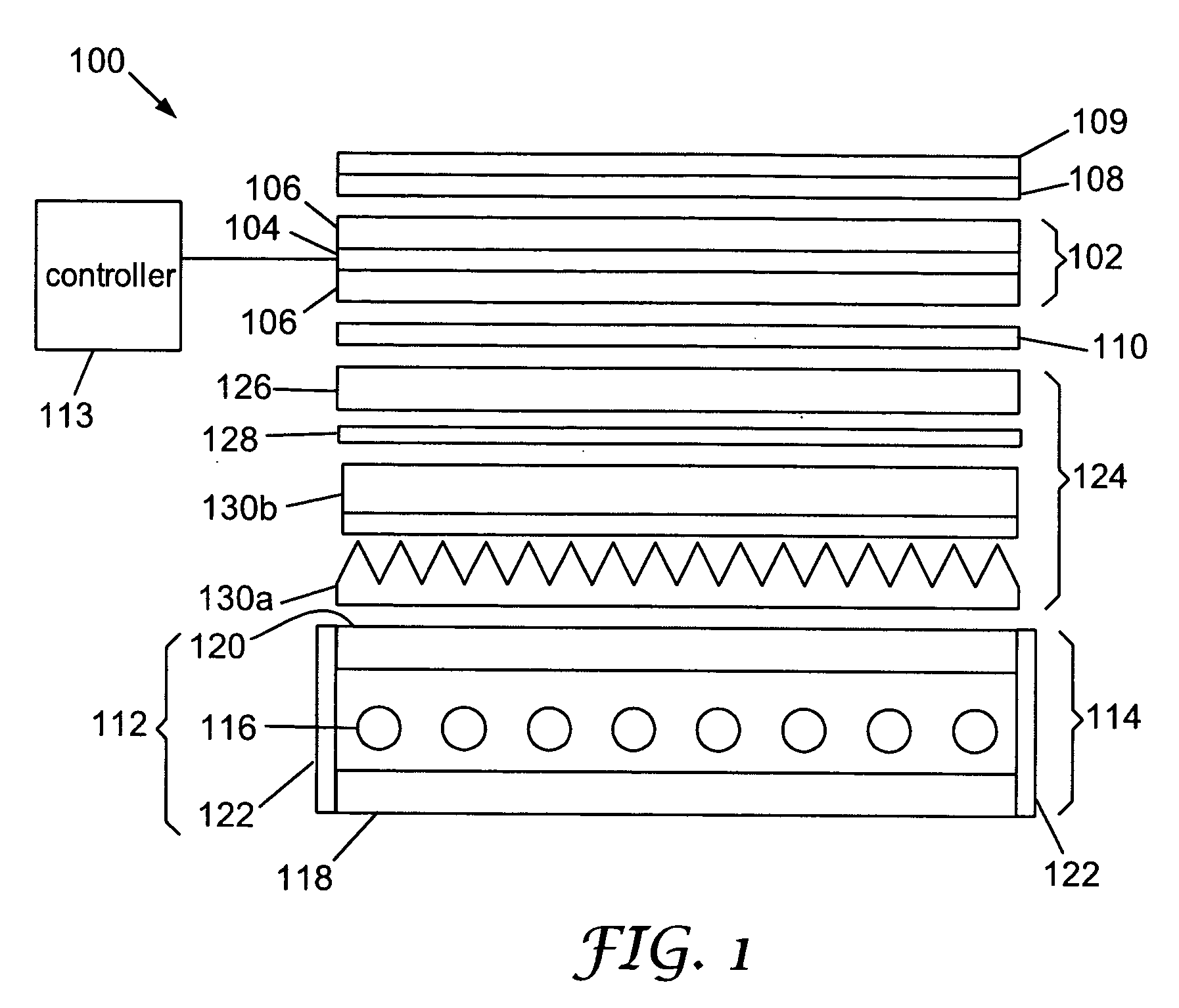
[0114] A controlled transmission mirror as described herein is not restricted to use for illuminating a liquid crystal display panel. The controlled transmission mirror may also be used wherever discrete light sources are used to generate light and it is desirable to have uniform illumination out of a panel that includes one of more of the discrete light sources. Thus, the controlled transmission mirror may find use in solid state space lighting applications and in signs, illuminated panels and the...
PUM
 Abstract
Description
Claims
Application Information