Liquid crystal driving electrode, liquid crystal display device, and manufacturing method thereof

a driving electrode and liquid crystal technology, applied in non-linear optics, instruments, optics, etc., can solve problems such as disturbances in liquid crystal domains, display may become rough or blocky, and above-described ips-lcds of the prior art still have unsolved problems, and achieve uniform and even display, excellent image quality, and low coloring

Active Publication Date: 2006-12-28
NEC LCD TECH CORP
View PDF6 Cites 41 Cited by
  • Summary
  • Abstract
  • Description
  • Claims
  • Application Information

AI Technical Summary

Benefits of technology

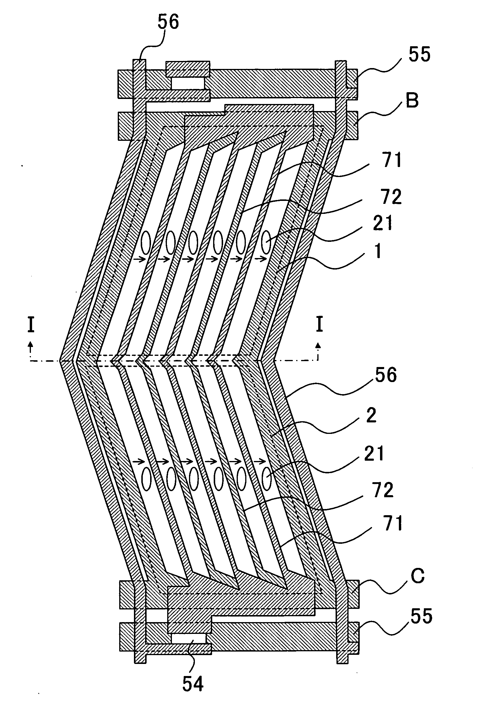
[0035] In the IPS-LCD of the present invention, the liquid crystal driving electrode is configured to have the double V shaped bent portions. This configuration stabilizes turning directions of the liquid crystal molecules in the vicinity of the boundary defined by the double V shaped bent portions. As a result, it is possible to obtain a liquid crystal display device having excellent image quality that can achieve uniform and even display with low coloring attributable to a change in a direction of a view angle.

Problems solved by technology

Nevertheless, the above-described IPS-LCDs of the prior art still have unsolved problems.
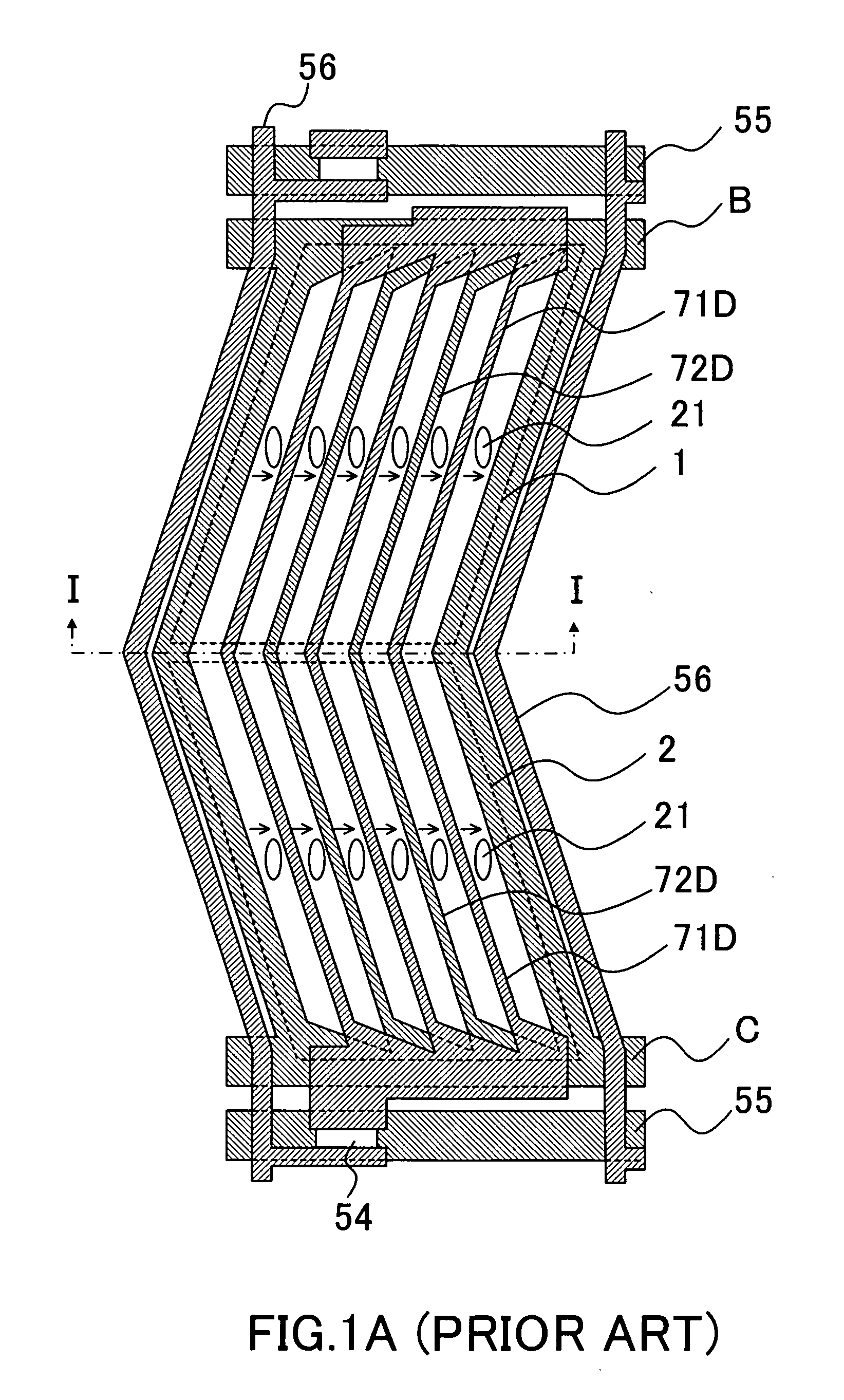
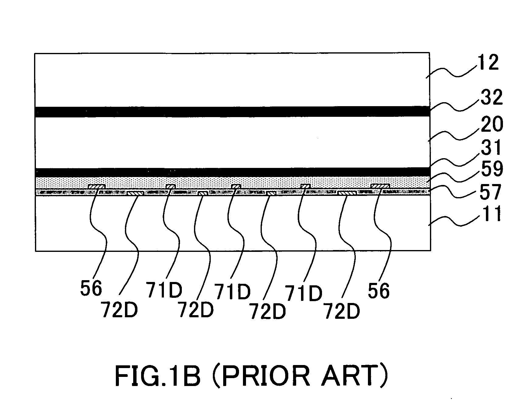
Specifically, disturbance in liquid crystal domains is apt to occur in the configuration shown in FIG. 1A due to the lack of a structure for stabilizing the boundary portions of the sub regions.
In such a case, the display may become rough or blocky.
Such a problem may be notable particularly when a panel is pressed with a finger.
That is, according to the prior art, it is not easy to set an appropriate angle for achieving the favorable voltage transmission rate characteristic while stabilizing the boundaries of the sub regions.
However, the relatively strong electric field in the vicinity of the protrusion still leads to a change in the aligning direction of the liquid crystal molecules in that case, thereby causing light leakage (a black blur) that triggers deterioration in display contrast.
In addition, this configuration also has a problem that a short circuit between electrodes is apt to occur in a region in the vicinity of the protrusion of the electrode where a distance between the liquid crystal driving electrodes is short.
For this reason, this configuration bears such a problem that it is not possible to define a uniform angle between the direction of extension of the electrode and the initial aligning direction of the liquid crystal in terms of the voltage transmission rate characteristic in sub region for the purpose of optimization.

Method used


Image

  • Liquid crystal driving electrode, liquid crystal display device, and manufacturing method thereof
  • Liquid crystal driving electrode, liquid crystal display device, and manufacturing method thereof
  • Liquid crystal driving electrode, liquid crystal display device, and manufacturing method thereof

Examples


first example

[0055] A first example of the present invention is similar to the LCD shown in FIG. 5A. As shown in FIG. 5A, this example has the configuration in which the pixel electrodes 71 and the common electrodes 72 have the double V shape at the bent portions thereof. Moreover, the angle defined between the direction of extension of the pixel electrodes 71 or the common electrodes 72 and the initial aligning direction (which is the vertical direction in the drawing) of the liquid crystal is set greater than the angles in other regions in the vicinity of the boundary between the sub regions. To be more precise, the angle defined between the direction of extension of the pixel electrodes 71 or the common electrodes 72 and the initial aligning direction of the liquid crystal is set to 15 degrees in the region mainly used for display, whereas the relevant angle is set to 45 degrees in the vicinity of the boundary between the sub region 1 and the sub region 2. Here, positive type liquid crystal i...

second example

[0079] An LCD according to a second example of the present invention will now be described with reference to FIG. 7. In this example, the number of bending a pixel is set to three times for each pixel as shown in FIG. 7. Therefore, each pixel has four sub regions. Specifically, in this example, a pixel electrode 71A and a common electrode 72A are bent three times. Other features of the LCD except the pixel electrodes 71A and the common electrodes 72A that are bent three times are similar to those in the configuration of the example shown in FIG. 5A.

[0080] In the configuration of this example as well, the turning directions of the liquid crystal molecules are stabilized in the vicinity of the boundary between the sub regions. Therefore, it is possible to perform even and stable display. Note that the LCD shown in FIG. 7 can be manufactured in accordance with a manufacturing method which is similar to the manufacturing method for the LCD shown in FIG. 5A.

third example

[0081]FIG. 8 is a plan view showing a configuration of a liquid crystal display device according to a third example of the present invention. In this example, the number of bending a pixel is set to five times for each pixel. Therefore, each pixel has six sub regions. Specifically, in this example, a pixel electrode 71b and a common electrode 72b are bent five times. Configurations except those of the pixel electrodes 71b and the common electrodes 72b that are bent five times are similar to the configuration of the example shown in FIG. 5A.

[0082] In the configuration of this example as well, the turning directions of the liquid crystal molecules are stabilized in the vicinity of the boundary between the sub regions. Therefore, it is possible to perform even and stable display. Note that the LCD shown in FIG. 8 can be manufactured in accordance with a manufacturing method which is similar to the manufacturing method of the LCD shown in FIG. 5A.


PUM

PropertyMeasurementUnit
angleaaaaaaaaaa
angleaaaaaaaaaa
driving voltageaaaaaaaaaa

Abstract

A liquid crystal display device of a multiple-domain in-plane switching mode applies to mutually engaged comb-shaped electrodes for each pixel region. The comb-shaped electrode has bent portions each in a double V shape which is formed as a comb-tooth pattern by causing a bent tip being bent into a V shape to protrude further outward. This structure stabilizes turning directions of liquid crystal molecules in the vicinity of a boundary between each two neighboring regions of multiple domains and suppresses display coloring attributable to a change in a view angle.

Description

BACKGROUND OF THE INVENTION [0001] 1. Field of the Invention [0002] The present invention relates to a liquid crystal driving electrode, and a liquid crystal display device (LCD), and a manufacturing method thereof. More specifically, the present invention relates to an active-matrix LCD (AM-LCD) applied to the in-plane switching (IPS) mode and a manufacturing method thereof. [0003] 2. Description of the Prior Art [0004] LCDs are generally characterized by thin profile, light weight, and low power consumption. In particular, AM-LCDs, which drive individual pixels arranged in a horizontal and vertical matrix by use of active elements, are regarded as high-quality flat panel display devices. Among them, thin film transistor LCDs (TFT-LCDs) applying thin film transistors (TFTs) as the active elements for switching the individual pixels are widely used. [0005] A conventional AM-LCD utilizes a twisted nematic (TN) type electro-optical effect. Moreover, liquid crystal molecules are sandwi...

Claims


Application Information

Patent Timeline
Patent Type & Authority Applications(United States)
IPC IPC(8): G02F1/1343
CPCG02F1/133707G02F2201/128G02F2201/124G02F1/134363G02F1/1343
Inventor SUZUKI, TERUAKI
Owner NEC LCD TECH CORP
Why Eureka
Try Eureka