Image projection apparatus and method of cooling an image projection apparatus

a technology of image projection apparatus and cooling method, which is applied in the direction of electrical apparatus construction details, instruments, television systems, etc., can solve the problems of increasing noise generation, deterioration of the function and operation of circuit components inside the image projection apparatus, and difficulty in rapid discharge of heat generated within the apparatus to outside the apparatus, so as to avoid increasing noise generation and/or a complicated structure, and maintain or improve the appearance of the apparatus. , the effect of small siz

Inactive Publication Date: 2006-12-28
SAMSUNG ELECTRONICS CO LTD
View PDF53 Cites 28 Cited by
  • Summary
  • Abstract
  • Description
  • Claims
  • Application Information

AI Technical Summary

Benefits of technology

[0009] The present general inventive concept provides an image projecting apparatus that effectively cools a plurality of heat generating units using a single cooling fan, thereby enabling image projecting apparatuses that are smaller in size while avoiding increase in noise generation and / or a complicated structure associated with a conventional image projecting apparatus, while maintaining or improving the appearance of the apparatus.

Problems solved by technology

However, this reduction in size and weight has led to various problems.
For example, the reduction in size has led to difficulty in the rapid discharge of heat that is generated within the apparatus to outside of the apparatus.
Failure to discharge this generated heat may cause a deterioration in the function and operation of circuit components inside of the image projecting apparatus.
However, conventional image projecting apparatuses that use a plurality of cooling fans generate an increased amount of noise, and conventional image projecting apparatuses that use a guiding unit have a complicated structure.

Method used


Image

  • Image projection apparatus and method of cooling an image projection apparatus
  • Image projection apparatus and method of cooling an image projection apparatus
  • Image projection apparatus and method of cooling an image projection apparatus

Examples


Embodiment Construction

[0027] Reference will now be made in detail to the embodiments of the present general inventive concept, examples of which are illustrated in the accompanying drawings, wherein like reference numerals refer to the like elements throughout. The embodiments are described below in order to explain the present general inventive concept by referring to the figures.

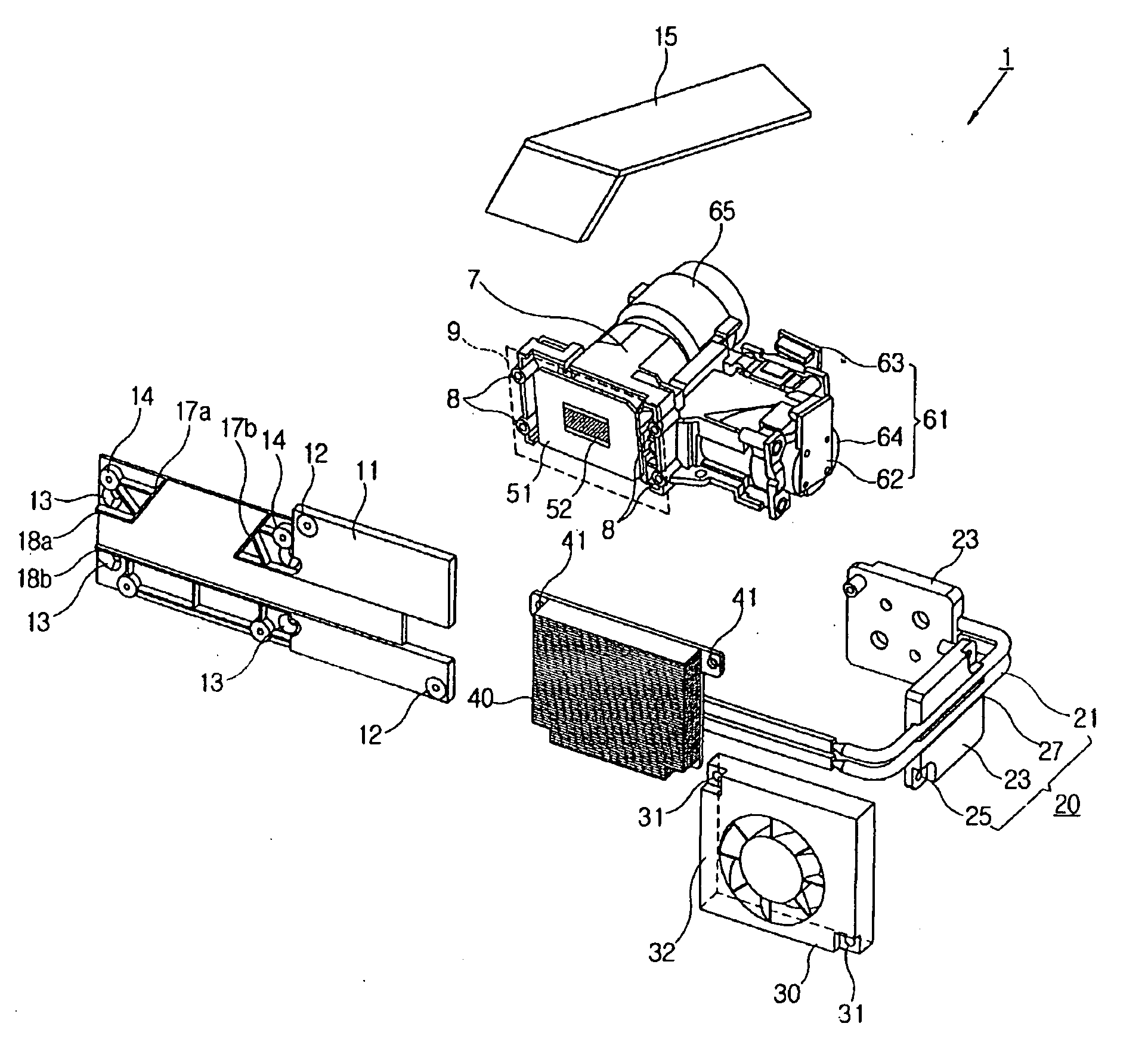
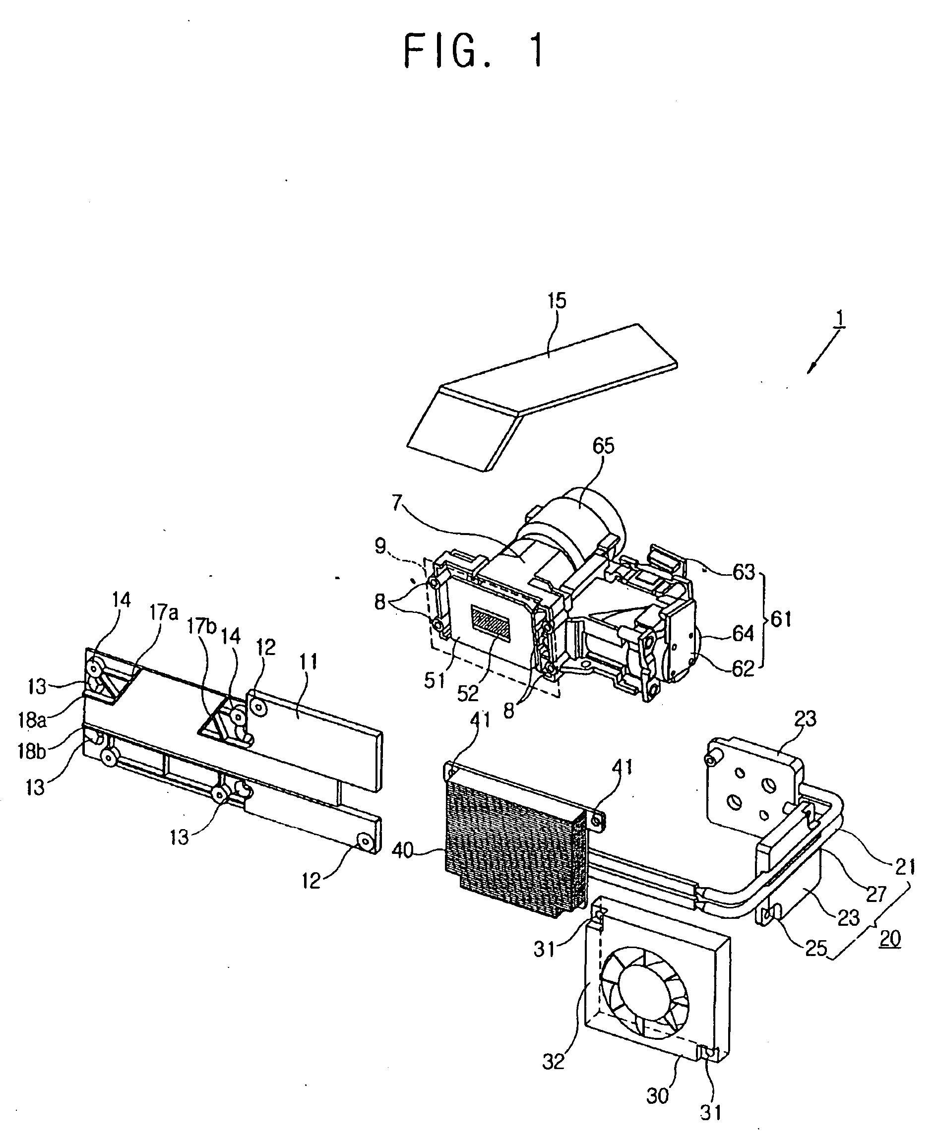
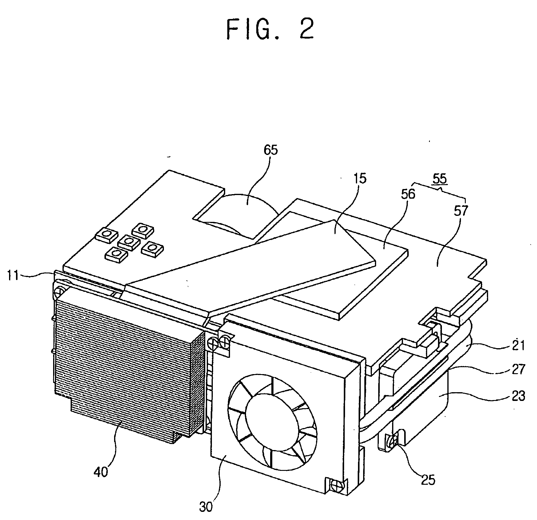
[0028]FIG. 1 is an exposed perspective view illustrating an image projecting apparatus according to an embodiment of the present general inventive concept. As illustrated in FIGS. 1-3, the image projecting apparatus 1 may include a housing (such as the housing 3 illustrated in FIG. 5), a main body frame 7 accommodated in the housing, a plurality of heat generating units 51, 55, and 61 supported by the main body frame 7 to generate heat during operation, cooling devices 11, 15, 20, 30, and 40 to cool the heat generating units 51, 55, and 61, and a projecting lens part 65.

[0029] The heat generating units may be selected from a ...


PUM


Abstract

An apparatus and method of cooling an image projecting apparatus. The image projecting apparatus includes a main body frame, at least one heat generating unit, a heat dispersion part, at least one heat transfer member, and a single cooling fan, where the first side of the at least one heat transfer member is connected to the at least one heat generating unit, and a second side of the at least one heat transfer member is connected to the heat dispersion part.

Description

CROSS-REFERENCE TO RELATED APPLICATIONS [0001] This application claims priority from Korean Patent Application No. 2005-33186, filed on Apr. 21, 2005, in the Korean Intellectual Property Office, which is hereby incorporated by reference in its entirety. BACKGROUND [0002] 1. Technical Field [0003] The present general inventive concept relates to an image projecting apparatus containing a cooling structure that cools at least one heat generating unit accommodated in the image projecting apparatus, as well as methods for cooling an image projecting apparatus. [0004] 2. Description of the Related Art [0005] Conventionally, an image projecting apparatus enlarges and projects an image formed by a display element onto a screen. Such a conventional image projecting apparatus includes a plurality of heat generating units that generate heat during operation. For example, a conventional image projecting apparatus often includes an optical system comprising a display element and a light source,...

Claims


Application Information

Patent Timeline
Patent Type & Authority Applications(United States)
IPC IPC(8): G03B21/18
CPCG03B21/16H05K7/2099H05K7/20972H04N9/3141H04N5/74
Inventor LIM, SEON-WOOKIM, WON-NYUN
Owner SAMSUNG ELECTRONICS CO LTD
Why Eureka
Try Eureka