Screw for kneading extruder

a technology of kneading extruder and screw, which is applied in the direction of mixing/kneading with horizontally mounted tools, clay mixing apparatus, rotary stirring mixers, etc., can solve the problem of limited working range of the engaged grooves of the screw segments

Inactive Publication Date: 2006-12-28
JAPAN STEEL WORKS LTD
View PDF8 Cites 10 Cited by
  • Summary
  • Abstract
  • Description
  • Claims
  • Application Information

AI Technical Summary

Benefits of technology

[0014] According to the invention, as described hereinbefore, the screw is constituted such that the screw includes: a screw shaft having engaging grooves of a predetermined shape formed in its outer circumference; and a plurality of screw segments having engaged grooves matching the engaging grooves of the screw shaft and adapted to be sequentially inserted on the screw shaft, and such that the engaged grooves of the screw segments are worked at their two end portions of the axial direction of the screw segments while leaving their intermediate portions as relief portions, in which the engaged grooves are not formed. In short, the working range of the engaged grooves of the screw segments is limited so that the screw can be manufactured, even if the axial length of the screw segments is large, at a working cost similar to that for the shorter ones. Since the working length is short, moreover, another advantage obtained is that the screw segments of a long axial length can be provided without deteriorating the working precision.

Problems solved by technology

In short, the working range of the engaged grooves of the screw segments is limited so that the screw can be manufactured, even if the axial length of the screw segments is large, at a working cost similar to that for the shorter ones.

Method used


Image

  • Screw for kneading extruder
  • Screw for kneading extruder
  • Screw for kneading extruder

Examples


Embodiment Construction

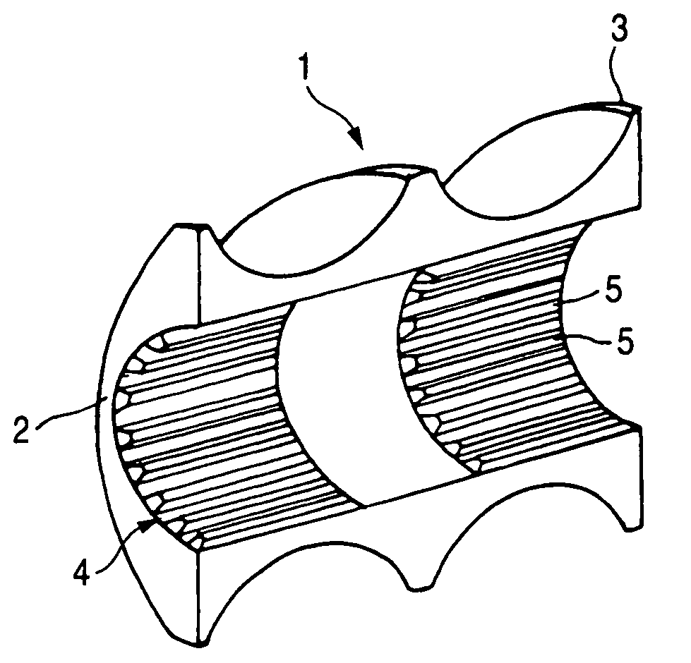
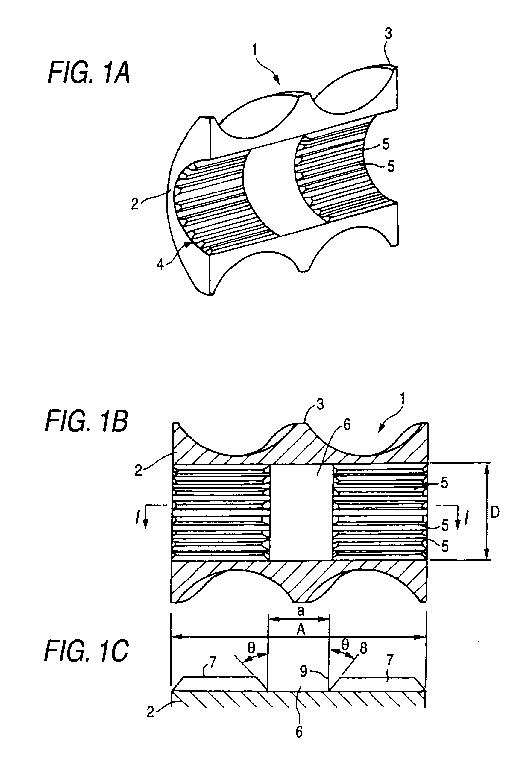
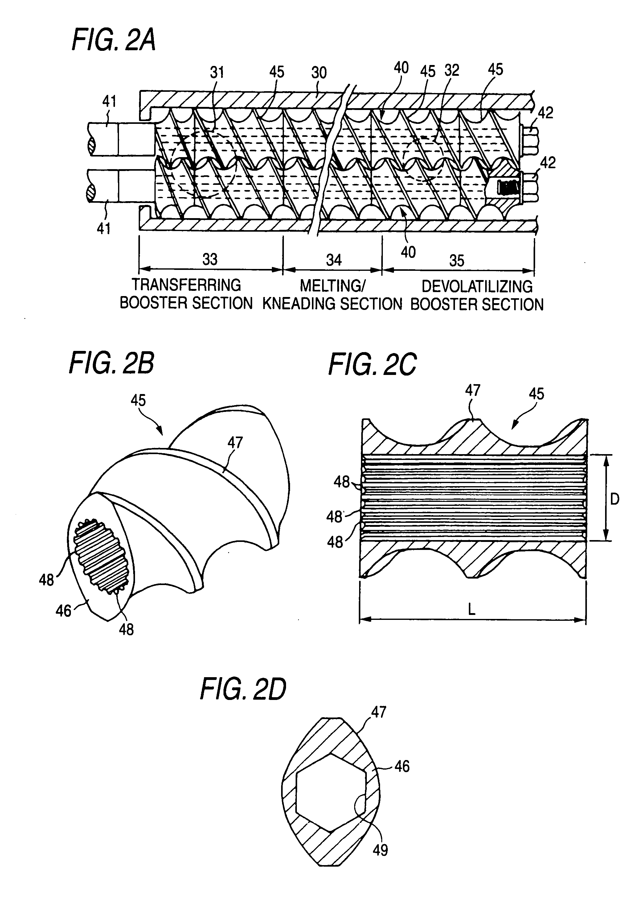
[0017] A mode of embodiment of the present invention is described with reference to FIG. 1. A screw segment according to this embodiment also has various flight shapes, as has been described with reference to FIG. 2. When the segment is suitably mounted on a screw shaft, a screw for an extruder having predetermined functions is constituted to have a predetermined length in the axial direction. However, only the screw segment having a standard flight is shown in FIG. 1.

[0018] A screw segment 1 according to this embodiment, as shown in FIG. 1, is also constituted to include a boss portion 2 and a spiral flight 3 formed integrally with that boss portion 2. In the center portion of the boss portion 2, there is formed a through hole 4 to be inserted on a screw shaft, as described hereinbefore. The screw segment 1 thus constituted has an axial length A, and the through hole has a diameter D. The ration A / D is made relatively large compared with the related art. In this embodiment, moreov...


PUM

PropertyMeasurementUnit
angleaaaaaaaaaa
circumferenceaaaaaaaaaa
lengthaaaaaaaaaa

Abstract

A screw for a twin-screw kneading extruder comprises a screw shaft having spline grooves formed therein, and a plurality of screw segments adapted to be inserted on that screw shaft. The spline grooves of the screw segments are formed in the two end portions of the axial direction of the screw segments, while leaving the intermediate portions as relief portions, in which the spline grooves are not formed. Since the intermediate portions need not be machined, the screw can be manufactured highly precisely, even if the axial length of the screw segments is large, at a working cost as low as that for the short ones.

Description

[0001] This application is based on Japanese Patent Application No. 2005-186012, which is incorporated herein by reference. BACKGROUND OF THE INVENTION [0002] 1. Field of the Invention [0003] The present invention relates to a screw for a kneading extruder and, more particularly, to a screw, which is rotationally driven in a cylinder to knead and melt a resin material fed from one end portion of the cylinder and to extrude the resin material from the other end portion. The invention relates to a screw for a kneading extruder such as a screw for a twin-screw kneading extruder, although not limitative. [0004] 2. Description of the Related Art [0005] A single-screw kneading extruder having one screw rotationally driven in a cylinder is well known in the art, although the document names are not enumerated. Also well known in the art is a twin-screw kneading extruder, which is constituted to include a cylinder and two screws so disposed in the cylinder as to be rotationally driven in the...

Claims


Application Information

Patent Timeline
Patent Type & Authority Applications(United States)
IPC IPC(8): B29B7/58B29C48/03
CPCB29C47/0009B29C47/60B29C47/0825B29C48/03B29C48/2564
Inventor KODATE, KAZUHIROINOUE, SHIGEKITSUSHIMA, HISATOSHI
Owner JAPAN STEEL WORKS LTD
Why Eureka
Try Eureka