
Receiver for digital modulated signal and receiving method for the same

a technology of digital modulation and receiving method, which is applied in the direction of digital transmission, baseband system, electrical apparatus, etc., can solve the problems of deteriorating reception performance, multi-path interference having such a long delay time, and extremely deteriorating reception performan

Active Publication Date: 2006-12-28
KK TOSHIBA
View PDF9 Cites 21 Cited by
  • Summary
  • Abstract
  • Description
  • Claims
  • Application Information

AI Technical Summary

Benefits of technology

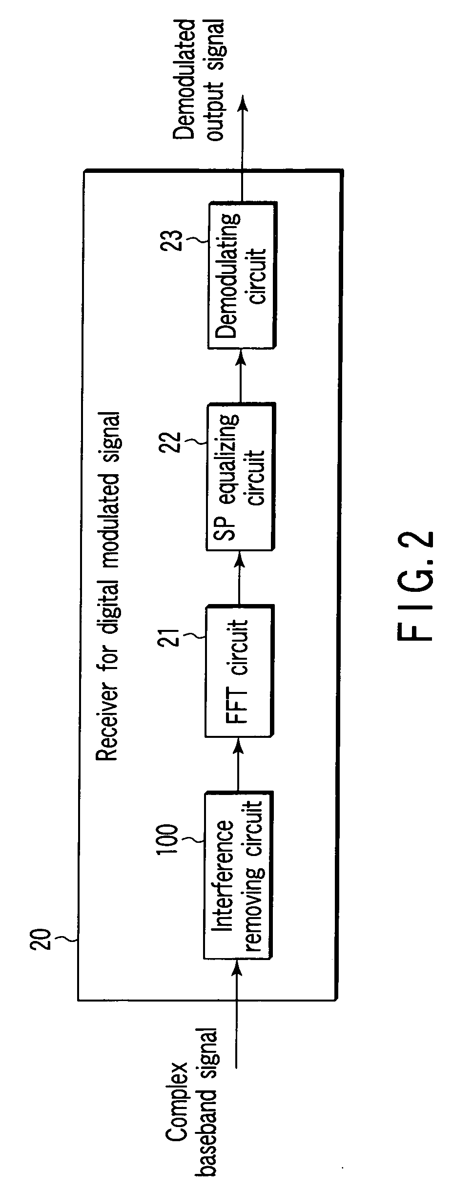
The present invention relates to a receiver and method for reducing interference in a digital modulated signal. The invention includes a Fourier transformer that performs Fourier transform of the receiving signal and an interference removing circuit that reduces ISI and ICI of the receiving signal. The interference removing circuit combines the interference removing components generated from the receiving signal on the basis of a transmission path response only during an appropriate period and outputs the receiving signal as it is during a period other than the appropriated period. The technical effect of the invention is to improve the quality of the received signal by reducing interference and improving the signal-to-noise ratio.

Problems solved by technology

However, the existence of a multi-path interference of a delay time longer than the guard interval length causes the ISI and the ICI to deteriorate reception performance.
The multi-path interference having such a long delay time presents a big problem in implementing a single frequency network (SFN).
However, if there is an estimated error in estimating the transmission path response resulting form temporal variations in noise and the transmission path response, a problem is produced such that each aforementioned conventional method cannot remove the interference components and also newly adds multi-path interference having a delay time that is integer multiple of a delay time of a delayed wave to the interference components to extremely deteriorate the reception performance.

Method used


Image

  • Receiver for digital modulated signal and receiving method for the same
  • Receiver for digital modulated signal and receiving method for the same
  • Receiver for digital modulated signal and receiving method for the same

Examples


first embodiment

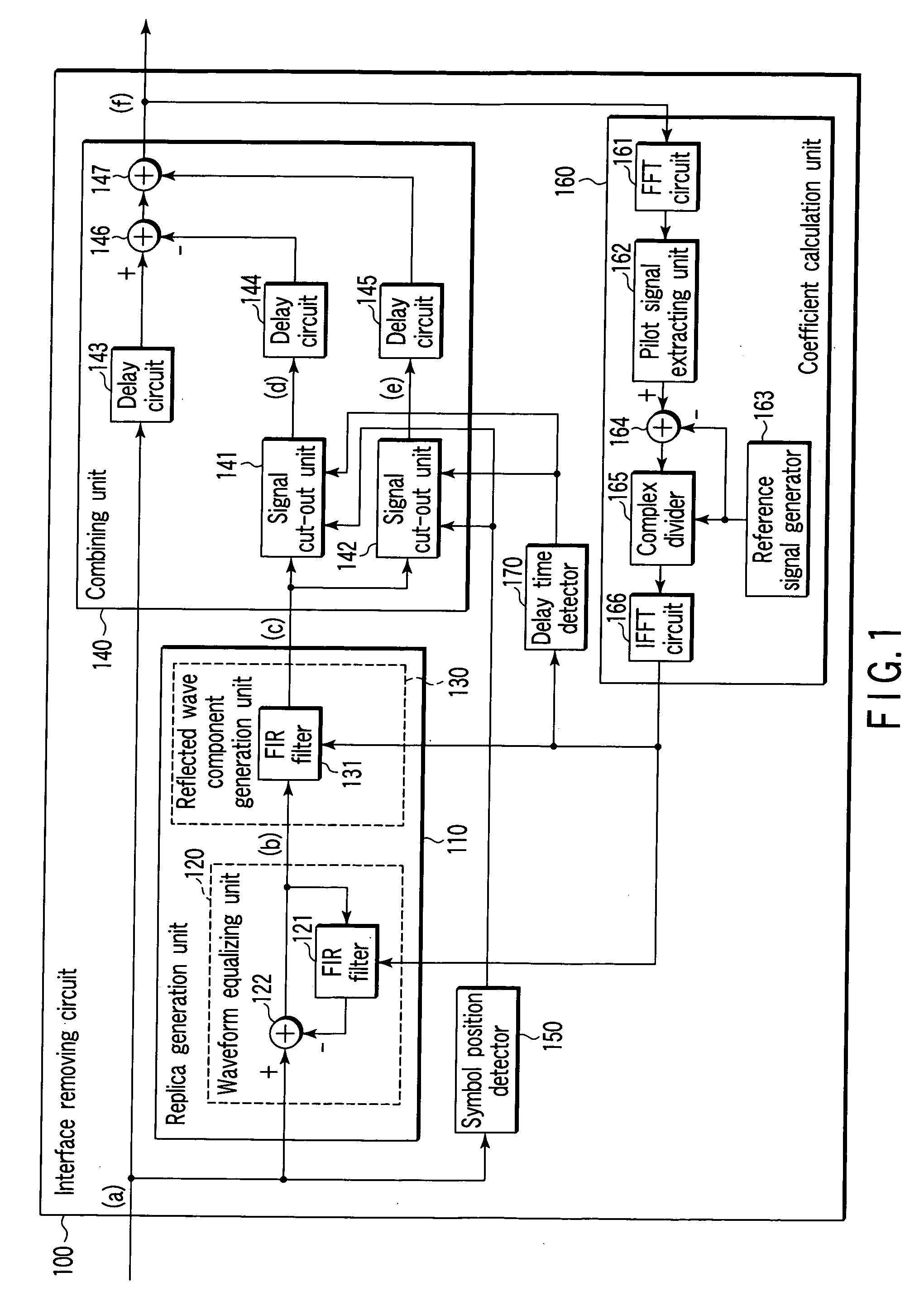
[0024] Referring to FIG. 1 to FIG. 4, FIG. 9 and FIG. 10, a first embodiment will be described.

[0025] A first embodiment relates to an Integrated services digital broadcasting for terrestrial (ISDB-T) (other embodiments go the same). In the following explanations, it is presumed that a scattered pilot (hereinafter referred to as SP) carrier that is an amplitude / phase reference is used as a reference signal in estimating a transmission path response.

[0026] The ISI and the ICI will be explained by referring to FIG. 9 and FIG. 10. FIG. 9 shows one transmission symbol of an OFDM. Because a signal component of a guard interval is the same as that of a rear section of an effective symbol, signal components belonging to the guard interval and to the rear section of the effective symbol are indicated, as shown in FIG. 9, as “A” and signal components belonging to other sections are indicated as “B” for simplifying the explanation. To express clearly the fact that the polarities of the sign...

second embodiment

[0069] Referring next to FIG. 5 and FIG. 6, a second embodiment will be set forth.

[0070] In particular, another embodiment in which a generation method and a combining method for a replica signal have been changed will be explained. The second embodiment is featured by firstly obtaining the difference between a signal resulting from delaying the receiving wave by the effective symbol period and the receiving wave, then, generates the replica signal on the basis of the difference signal. The case in which the interference removing circuit of the second embodiment appropriately selects the result of combination of the receiving wave and the replica signal over the whole period and the receiving wave to output it is also exemplified.

[0071]FIG. 5 is the block diagram showing the configuration of the interference removing circuit in the second embodiment. The removing circuit is applied to the receiver for the digital modulated signal 20.

[0072] The removing circuit 100 comprises the s...

third embodiment

[0085] In succession, a third embodiment will be described by referring to FIG. 7 and FIG. 8.

[0086] Other embodiment varying the generation method and combining method for the replica signal will be described. The third embodiment is featured by setting a signal cut-out unit in front of a reflected wave component generation unit. Such a configuration enables the delay time detection circuit to be omitted.

[0087]FIG. 7 is the block diagram showing the configuration of the interference removing circuit 100 in the third embodiment. The removing circuit 100 is applied to the receiver for the digital modulated signal 20 shown in FIG. 2.

[0088] The removing circuit 100 comprises the symbol position detector 150 detecting the breaks of the transmission symbol from the input signal, an inter-symbol difference generation circuit 570 outputting the difference (inter-symbol difference signal) between the input signal and a signal resulting from delaying the input signal by the time of the eff...


PUM


Abstract

A receiver for a digital modulated signal which receives a multi-carrier modulated signal and demodulates a receiving signal by converting it from a time region into a frequency region by Fourier transform is provided. The receiver comprises a Fourier transformer which performs Fourier transform of the receiving signal and an interference removing circuit which reduces an inter-symbol interference or an inter-carrier interference of the receiving signal. The removing circuit is disposed in a front stage of the Fourier transformer.

Description

CROSS-REFERENCE TO RELATED APPLICATIONS [0001] This application is based upon and claims the benefit of priority from prior Japanese Patent Application No. 2005-183007, filed Jun. 23, 2005, the entire contents of which are incorporated herein by reference. BACKGROUND OF THE INVENTION [0002] 1. Field of the Invention [0003] The present invention relates to a receiver for a digital modulated signal and a receiving method for the same, which receives a muti-carrier modulated signal extremely reduced in an inter-symbol interference (hereinafter referred to as ISI) or in an inter-carrier interference (hereinafter referred to as ICI). [0004] 2. Description of the Related Art [0005] In recent years, a digital modulation method has been widely developed in a transmission of a sound signal and a video signal. In particular, a multi-carrier modulation method has attracted attention in the fact that it has a high resistance to a multi-path interference because it can expand its symbol period l...

Claims


Application Information

Patent Timeline
Patent Type & Authority Applications(United States)
IPC IPC(8): H04J11/00
CPCH04L25/03038H04L27/2647H04L25/03821H04L2025/03477H04L2025/03414
Inventor NISHIKAWA, MASAKI
Owner KK TOSHIBA
Learn More