
Data link/physical layer packet buffering and flushing

a data link and physical layer technology, applied in the field of network work, can solve the problems of unscalable architectures for the type of efficient, high speed

Active Publication Date: 2006-12-28
XYLON LLC
View PDF18 Cites 7 Cited by
  • Summary
  • Abstract
  • Description
  • Claims
  • Application Information

AI Technical Summary

Problems solved by technology

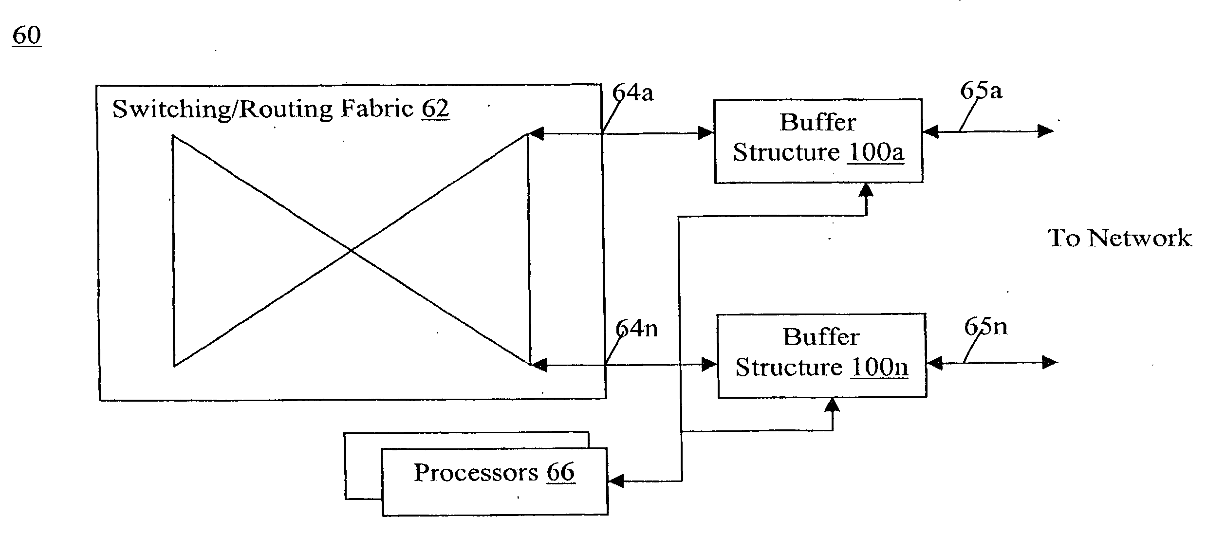
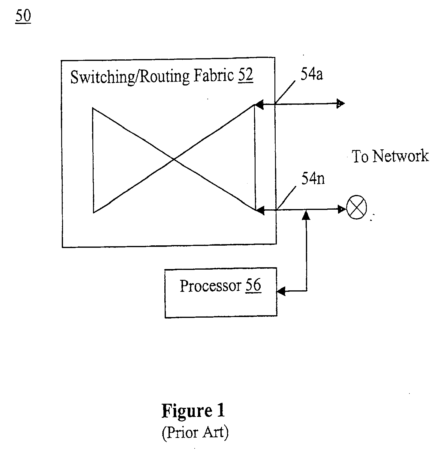
These prior art approaches all suffer from the common disadvantage in that at least one of the ingress / egress point of switching / routing fabric 52 is used for the coupling of a host processor 56.
Increasingly, these architectures are becoming un-scalable for the type of efficient, high speed (10 Gb and beyond) networking that spans local, regional, and wide area networks, especially when multiple datacom and telecom protocols are involved.

Method used


Image

  • Data link/physical layer packet buffering and flushing
  • Data link/physical layer packet buffering and flushing
  • Data link/physical layer packet buffering and flushing

Examples


Embodiment Construction

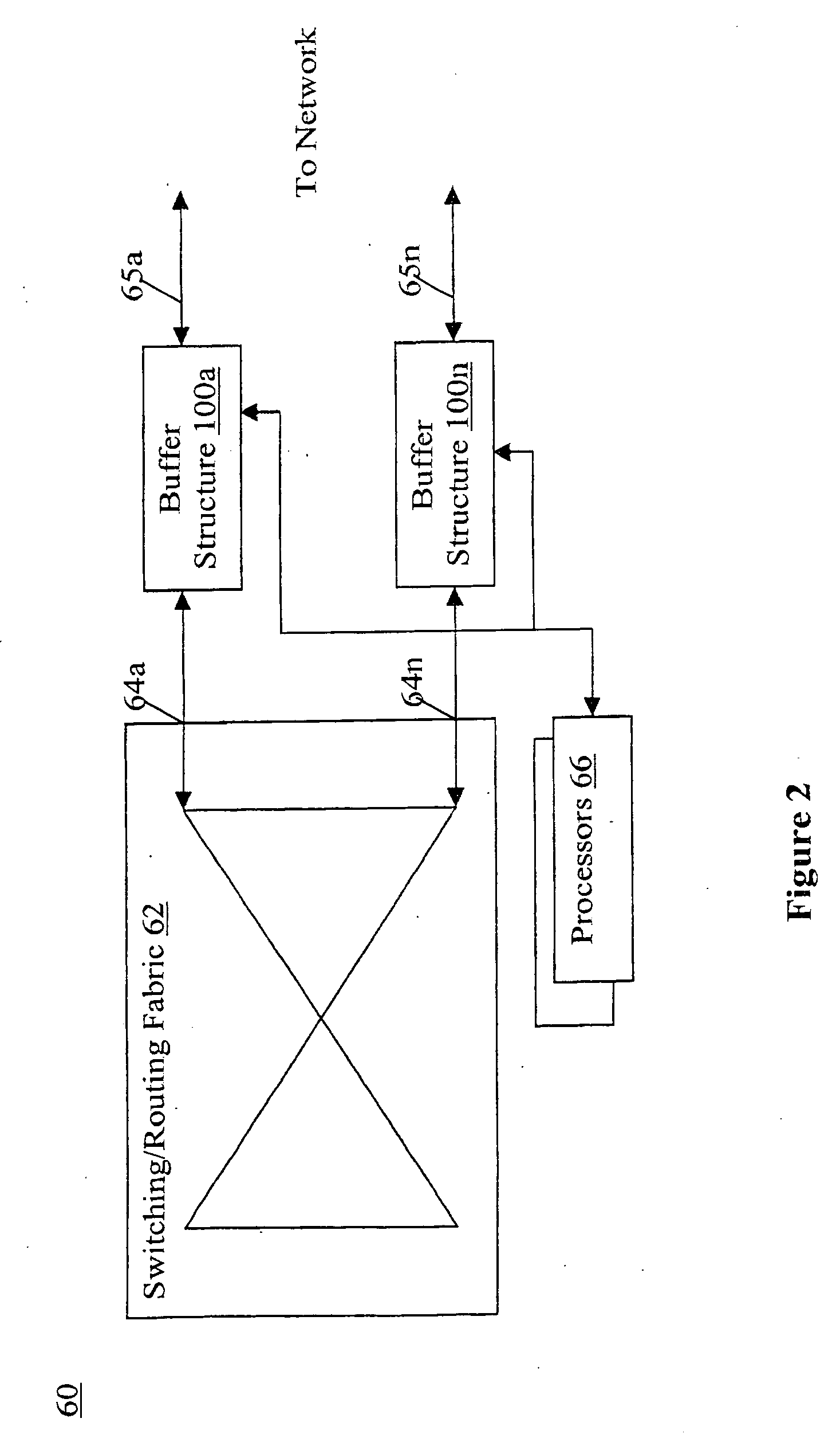
[0022] The present invention includes a buffering structure having storage structures and associated packet diversion and insertion logic to facilitate post-switching, pre-medium placement diversion and / or insertion of egress packets, and / or post-medium extraction, pre-switching diversion and / or insertion of ingress packets, in particular, during data link / physical layer processing of the ingress and / or egress packets. In another aspect, the buffering structure further includes selective tail and head flushing of the buffered packets. Both aspects address support for multiple datacom and telecom protocols.

[0023] In the following description, various aspects of the present invention will be described. However, the present invention may be practiced with only some aspects of the present invention. For purposes of explanation, specific numbers, materials and configurations are set forth in order to provide a thorough understanding of the present invention. However, the present inventi...


PUM


Abstract

A buffering structure including at least a first FIFO storage structure to stage at least a selected one of undiverted egress packets and undiverted ingress packets is provided. The buffering structure further includes at least first associated packet drop logic to selectively effectuate head or tail flushes of the first FIFO storage structure. In various embodiments, one or more additional FIFO storage structures are also provided to stage one or more diverted and / or insertion of egress / ingress packets. Those use for staging diverted egress / ingress packets are likewise provided with associated packet drop logic to perform tail flushes of these additional FIFO structures. In one application, the buffering structure is employed by a multi-protocol network processor, which in turn is employed by an optical networking module.

Description

BACKGROUND OF THE INVENTION [0001] 1. Field of the Invention [0002] The present invention relates to the field of networking. More specifically, the present invention relates to packet buffering and flushing for high-speed network trafficking equipment, such as 10-gigabit optical-electrical routers or switches. [0003] 2. Background Information [0004] With advances in integrated circuit, microprocessor, networking and communication technologies, increasing number of devices, in particular, digital computing devices, are being networked together. Devices are often first coupled to a local area network, such as an Ethernet based office / home network. In turn, the local area networks are interconnected together through wide area networks, such as SONET networks, ATM networks, Frame Relay, and the like. Of particular importance is the TCP / IP based global inter-network, the Internet. [0005] As a result of this trend of increased connectivity, increasing number of applications that are netw...

Claims


Application Information

Patent Timeline
IPC IPC(8): H04L12/56
CPCH04L49/30H04L49/9078H04L49/9047H04L49/90
Inventor PRIMROSE, DONALD R.DENTON, I. CLAUDE
Owner XYLON LLC
Learn More