Digital TV broadcast signal receiving system and outdoor appliance used therein

a digital tv and broadcast signal technology, applied in the direction of information relaying between terminal devices, television systems, selective content distribution, etc., can solve the above-mentioned problems of the conventional tv broadcast signal receiving system, the tv broadcast signal receiver cannot receive the digital tv broadcast signal, and the increase of the working charg

Inactive Publication Date: 2006-12-28
FUNAI ELECTRIC CO LTD
View PDF4 Cites 19 Cited by
  • Summary
  • Abstract
  • Description
  • Claims
  • Application Information

AI Technical Summary

Benefits of technology

[0014] By such a configuration, the reception channel of the tuner can be changed from the indoor appliance, and the user can select the reception channel like the conventional digital TV broadcast signal receiving system without uncomfortable feeling.

Problems solved by technology

In such a conventional digital TV broadcast signal receiving system, wiring operation for laying and connecting the cables 122 from the antenna 131 for terrestrial digital TV broadcast and the antenna 132 for satellite digital TV broadcast placed in the outdoor location to the set top box 120 placed in the indoor location is complex and troublesome, so that it causes the increase of the cost for working charge.
Thus, for example, in a personal computer into which no tuner and no demodulator are installed cannot receive the TV broadcast signal.
In addition, the TV broadcast signal receiver cannot receive the digital TV broadcast signal.
In such a communication antenna system, the outdoor appliance and the indoor appliance are connected with the coaxial cable similar to the conventional TV broadcast signal receiving system shown in FIG. 4, so that the above-mentioned problems of the conventional TV broadcast signal receiving system cannot be solved.

Method used


Image

  • Digital TV broadcast signal receiving system and outdoor appliance used therein
  • Digital TV broadcast signal receiving system and outdoor appliance used therein
  • Digital TV broadcast signal receiving system and outdoor appliance used therein

Examples


Embodiment Construction

[0020] A digital TV broadcast signal receiving system in accordance with an embodiment of the present invention is described with reference to figures.

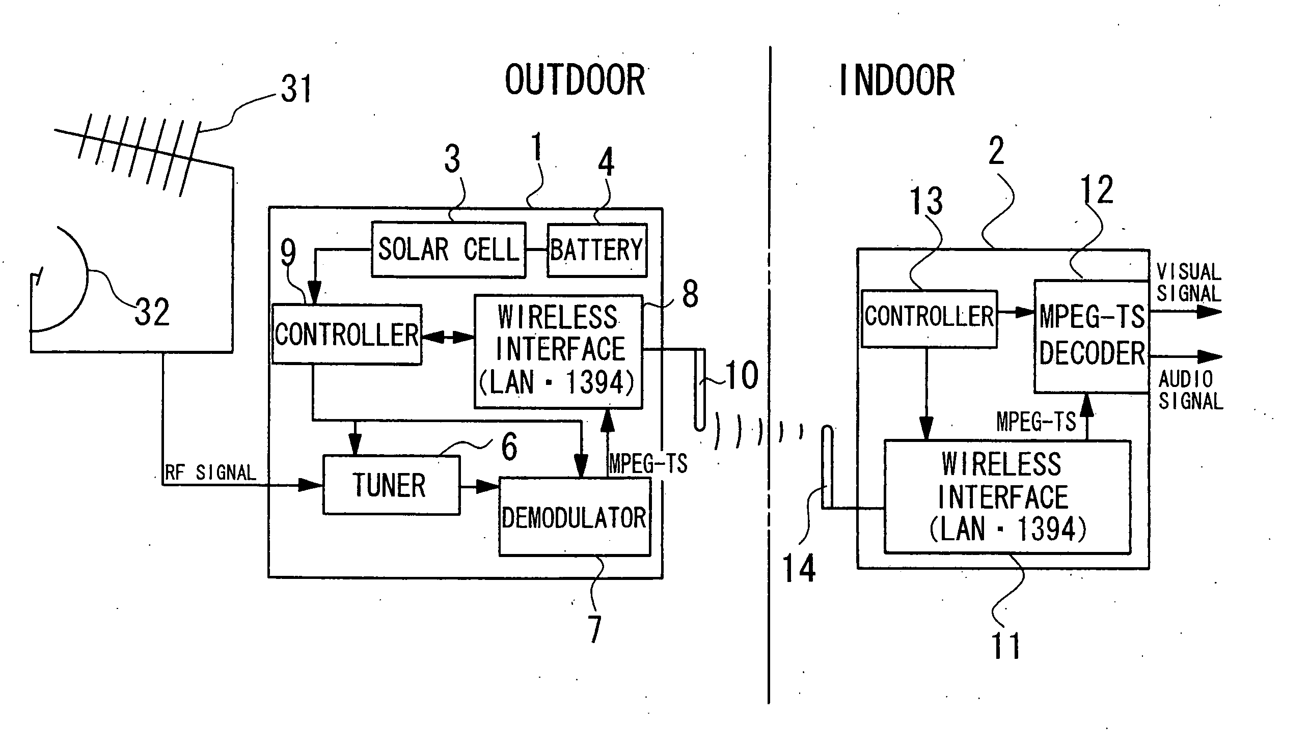
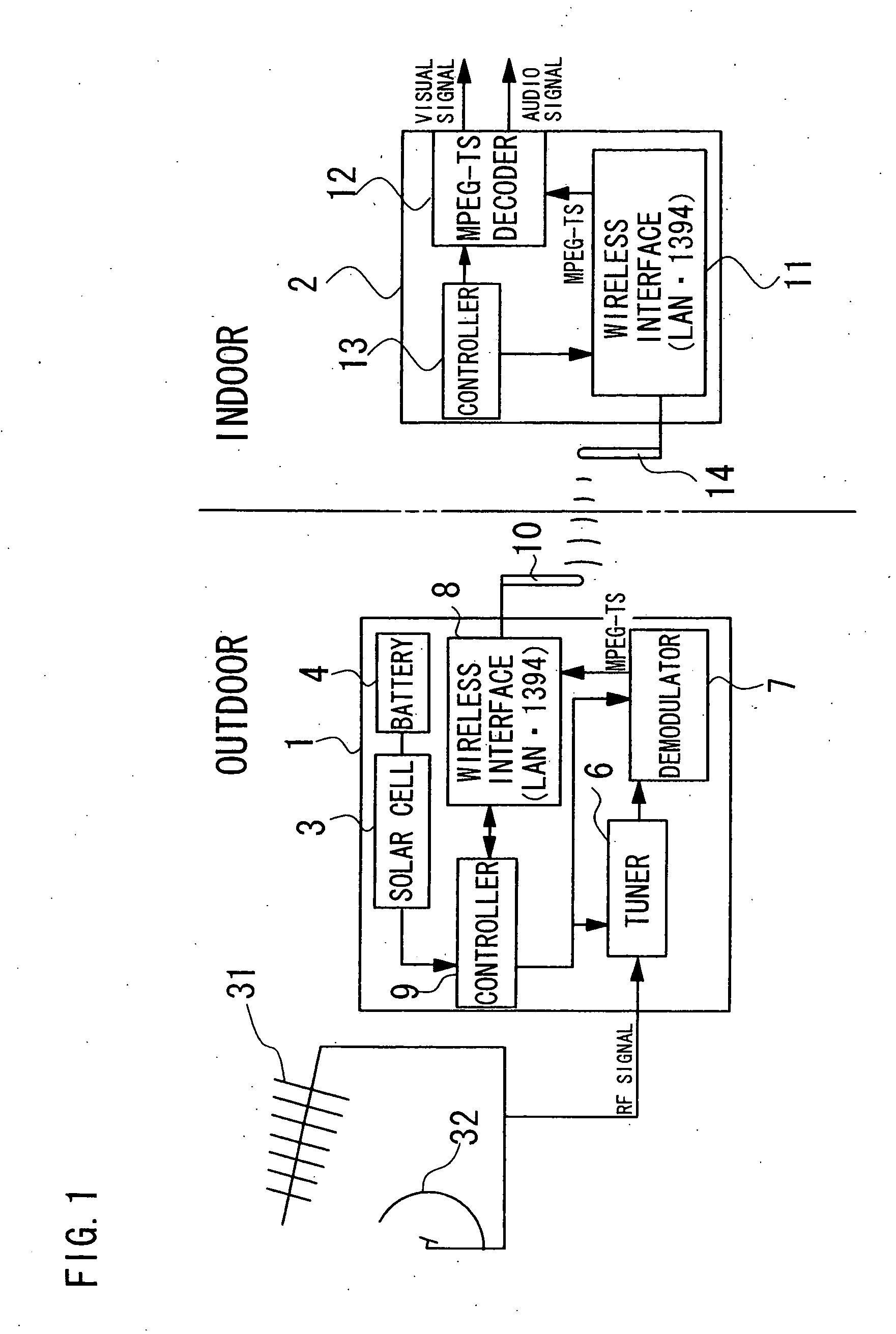
[0021]FIG. 1 shows a configuration of the digital TV broadcast signal receiving system. An antenna 31 for receiving a terrestrial digital TV broadcast signal and an antenna 32 for receiving a satellite digital TV broadcast signal placed in an outdoor location are connected to this digital TV broadcast signal receiving system. An outdoor appliance 1 which is directly connected to the antenna 31 for terrestrial digital TV broadcast and the antenna 32 for satellite digital TV broadcast is located in the vicinity of these antennas 31 and 32, for example, on an exterior wall of a user's house, and an indoor appliance 2 is placed in the vicinity of, for example, a monitor apparatus such as an LCD display (not illustrated).

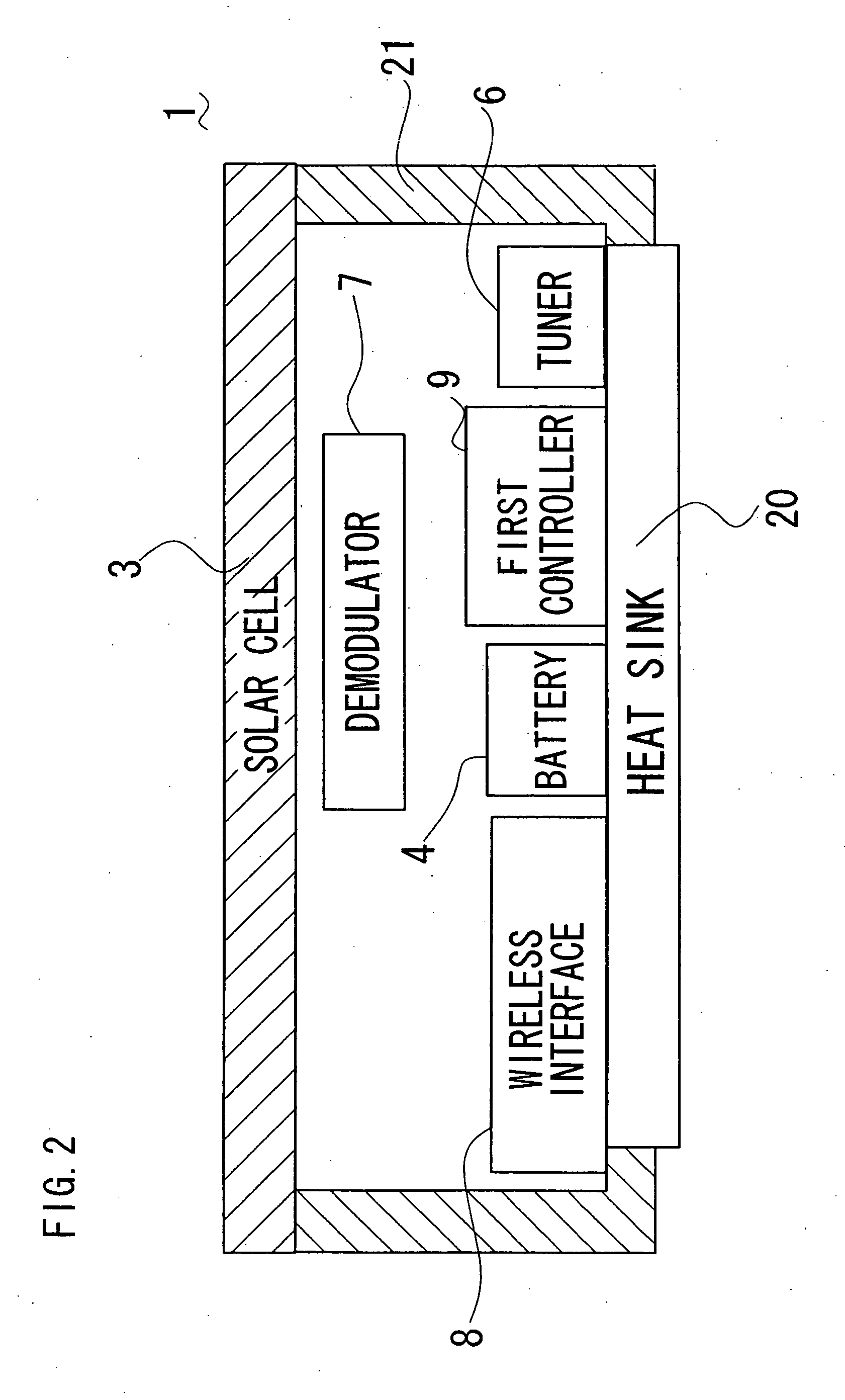
[0022] The outdoor appliance 1 is comprised of a solar cell (photovoltaic means) 3 which generates electric power by r...


PUM


Abstract

In a digital TV broadcast signal receiving system, an outdoor appliance comprises a tuner for receiving a TV broadcast signal transmitted from a TV tower or a broadcast satellite, a signal demodulator for demodulating the TV broadcast signal, and a first wireless interface for transmitting data with a second wireless interface provided in an indoor appliance. The indoor appliance further has a signal decoder for separating an audio signal and a visual signal and outputs them to a monitor apparatus. An appliance such as a personal computer having no tuner circuit can receive the TV broadcast signal if it has a wireless interface such as a wireless LAN. Furthermore, the data communication between the outdoor appliance and the indoor appliance is performed by wireless interfaces, so that a cable connecting between an outdoor appliance and an indoor appliance can be omitted.

Description

BACKGROUND OF THE INVENTION [0001] 1. Field of the Invention [0002] The present invention relates to a digital TV (television) broadcast signal receiving system which receives a terrestrial digital TV broadcast signal and a satellite digital TV broadcast signal and an outdoor appliance used therein. [0003] 2. Description of the Related Art [0004] As shown in FIG. 3, a conventional digital TV broadcast signal receiving system is a set top box 120 including a tuner 106, a signal demodulator 107, a signal decoder 112, a control unit 113 for controlling each department of the set top box 120, and so on. An antenna 131 for receiving a terrestrial digital TV broadcast signal and an antenna 132 for receiving a satellite digital TV broadcast signal are placed in an outdoor location. On the other hand, the set top box 120 is placed in an indoor location such as an interior of a user's house. Therefore, coaxial cables 122 for transmitting a broadcast signal (RF signal) received by the antenna...

Claims


Application Information

Patent Timeline
Patent Type & Authority Applications(United States)
IPC IPC(8): H04N7/20H04B1/06H04H1/00H04H20/00H04H20/06H04H20/08H04H60/92H04N5/00H04N5/44
CPCH04H20/06H04H20/08H04H40/90H04N21/43632H04N21/4122H04N21/41407H04N21/43615H04H60/92
Inventor MATSUO, MASAHIRO
Owner FUNAI ELECTRIC CO LTD
Why Eureka
Try Eureka