Leak detection system with wireless remote unit

a leak detection and wireless remote technology, applied in the direction of fluid tightness measurement, electric testing/monitoring, instruments, etc., can solve the problem that the operator is not able to spray helium onto the vacuum vessel at the remote location, the amount of helium detected represents a leak rate,

Inactive Publication Date: 2007-01-04
VARIAN INC
View PDF6 Cites 70 Cited by
  • Summary
  • Abstract
  • Description
  • Claims
  • Application Information

AI Technical Summary

Problems solved by technology

The amount of helium detected represents a leak rate.
In addition, test equipment and other objects may clutter the area around the unit under test.
Thus, the operator is not able to spray helium onto the vacuum vessel at the remote location and, at the same time, observe the leak rate measured by the leak detector.
However, two operators may not readily be available.
Further, the process involves coordination by verbal communication to localize a leak and thus involves inconvenience and possible frustration.
While this arrangement is satisfactory in principle, the cable may be too short to reach a location of interest or may become entangled in components of the unit under test and equipment that surrounds the unit under test.
Therefore, the cable-connected display unit only partially alleviates the difficulties in detecting leaks in large syste

Method used


Image

  • Leak detection system with wireless remote unit
  • Leak detection system with wireless remote unit
  • Leak detection system with wireless remote unit

Examples


Embodiment Construction

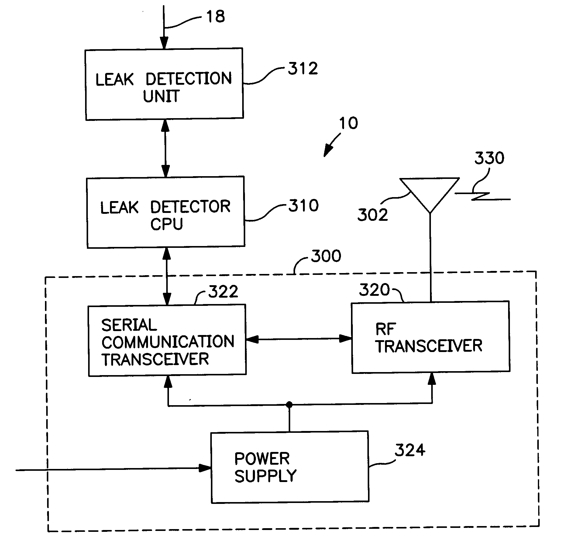
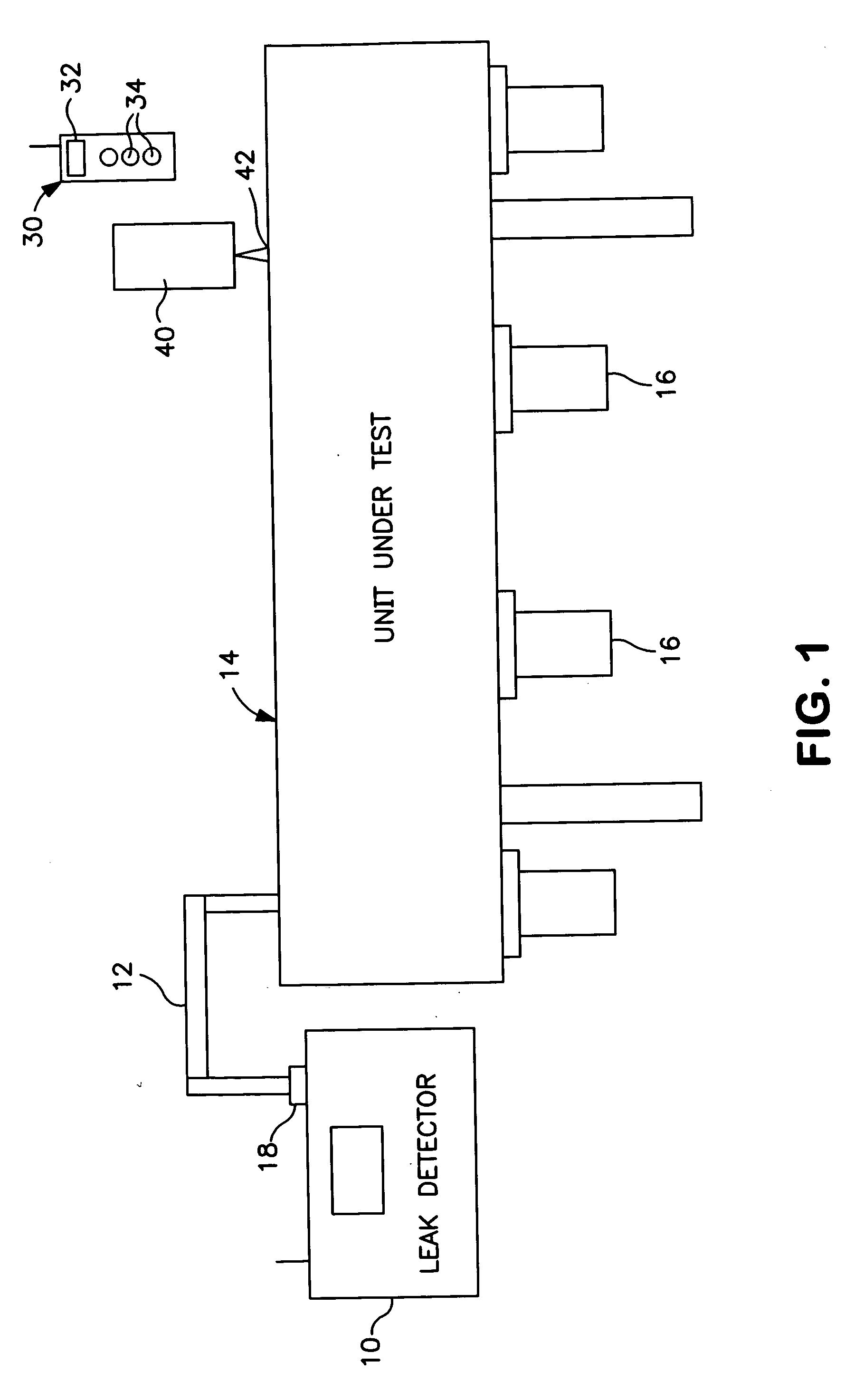
[0024] A schematic block diagram of a leak detection system in accordance with an embodiment of the invention is shown in FIG. 1. A leak detector 10 is connected by a vacuum connection 12 to a unit under test 14. Unit under test 14 may be any equipment having a sealed chamber or vessel that requires leak testing. In a non-limiting example, the leak detection system may be used to detect leaks in the vacuum vessel of processing equipment used in the fabrication of semiconductor wafers. The unit under test 14 may include one or more vacuum pumps 16 for evacuating the unit under test 14. The invention is most useful for testing a large unit under test but can be utilized for leak detection in a sealed chamber of any size.

[0025] Leak detector 10 is a trace gas leak detection instrument that detects leaks by sensing a trace gas, such as helium, that passes through a leak in a sealed chamber. Leak detector 10 has a display of leak rate and may include various controls, depending on its c...


PUM


Abstract

A leak detection system includes a trace gas leak detector having a wireless base unit, and a handheld wireless remote unit to generate an alphanumeric display of leak rate measured by the leak detector, in response to leak detector information received by wireless link from the leak detector. The remote unit may include a wireless transceiver to communicate with the wireless base unit of the leak detector, a display unit and a controller, responsive to the received leak detector information, to generate the display on the display unit. The remote unit may be configured to control the leak detector and may be configured to display a leak detector operating mode.

Description

FIELD OF THE INVENTION [0001] This invention relates to trace gas leak detection systems and, more particularly, to leak detection systems and methods which utilize a handheld wireless remote unit to display leak detector operating information. BACKGROUND OF THE INVENTION [0002] Helium mass spectrometer leak detection is a well-known leak detection technique. Helium is used as a tracer gas which passes through the smallest of leaks in a unit under test. After passing through a leak, a test sample containing helium is drawn into a leak detector and is measured. An important component of the leak detector is a mass spectrometer tube which detects and measures the helium. The input test sample is ionized and mass analyzed by the spectrometer tube in order to separate and measure the helium component. The unit under test may include a sealed chamber that may be large or small. The sealed chamber may be a vacuum vessel that is to be tested for leaks. [0003] In one mode of operation of th...

Claims


Application Information

Patent Timeline
Patent Type & Authority Applications(United States)
IPC IPC(8): G01M3/04
CPCG01M3/226G01M3/205G08B25/10G08C17/02G05B23/02G08C2201/00F17C2260/038
Inventor YAMARTINO, STEPHEN J.GEIST, DANIELKLEBANOV, JOSEPH
Owner VARIAN INC
Why Eureka
Try Eureka