Pressure transmitter

Inactive Publication Date: 2007-01-04
VEGA GRIESHABER GMBH & CO
View PDF9 Cites 11 Cited by
  • Summary
  • Abstract
  • Description
  • Claims
  • Application Information

AI Technical Summary

Benefits of technology

[0008] Advantageously, optimal temperature compensation of the pressure transmitter and hence of the pressure gauge is achieved in a simple manner. An advantage of the pressure transmitter according to the invention is that the pressure transmitter head does not have to be enlarged to produce the temperature compensation. Moreover, no additional expensive manufacturing process steps are required. Once a pressure transmitter is specified—namely over the appropriate selection of coefficients of thermal expansion the compensating volume of the separating membrane an

Problems solved by technology

This often results in relatively large measurement errors.
However, the volume of the pressure-transmitting medium cannot be reduced at will because of the desired measuring range of the pressure sensor or its measurement tolerances.
Moreover, a pressure transmitter with a very small separating membrane diameter is often required, since space considerations alone often place limits on the size of the separating membrane in terms of area.
However,

Method used


Image

  • Pressure transmitter
  • Pressure transmitter

Examples


Embodiment Construction

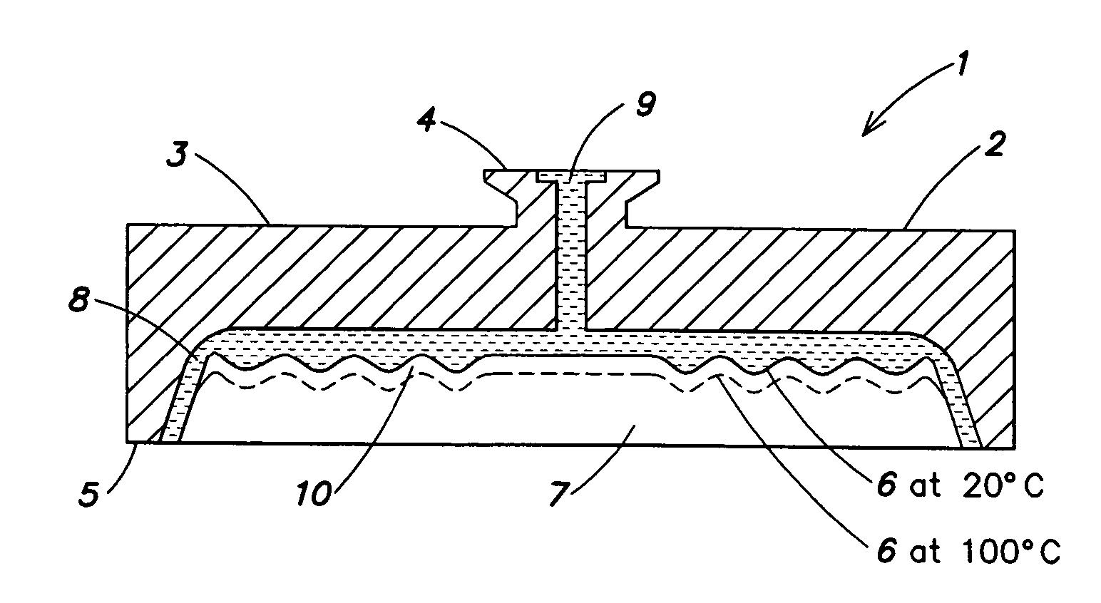
[0016]FIG. 1 is a partial section through a pressure transmitter 1, of a pressure gauge. The pressure transmitter 1 includes a metal pressure transmitter base body 2, which preferably includes a corrosion-proof oxidation-resistant material. However, the base body 2 may include at least partially another material such as for example a ceramic material. On a sensor side 3, the base body 2 has a flange 4 that connects the pressure transmitter 1 with a pressure sensor (not shown).

[0017] On a process side 5, the pressure transmitter 1 has a separating membrane 6 disposed in a recess 7 formed in base body 2. The membrane 6 is disposed in the recess 7 in such a way that a chamber 8 is formed between the membrane 6 and the base body 2. In addition, the base body 2 of the pressure transmitter 1 has a hole 9 connected with the chamber 8 and with the flange 4. A pressure-transmitting medium (e.g., an oil) is located in the communicating chamber 8 and the hole 9. The membrane 6 separates mediu...


PUM


Abstract

The invention relates to a pressure transmitter for an overload-proof pressure gauge, comprising a base body, a separating membrane disposed on a pressure-sensitive side of the pressure transmitter and subjectable to a pressure to be measured, a communicating chamber located inside said base body, which receives a pressure transmission medium, said chamber being closed on the pressure-sensitive side by the separating membrane, wherein the coefficient of thermal expansion of the pressure transmission medium is established in such a way that a temperature-induced change in the volume of the communicating chamber equals a temperature-induced change in the volume of the pressure transmission medium.

Description

PRIORITY INFORMATION [0001] This application is a continuation of co-pending Ser. No. 10 / 312,975 filed Dec. 30, 2002.BACKGROUND OF THE INVENTION [0002] The present invention relates to the field of pressure transducers, and in particular to the field of pressure transducers that include a temperature compensated pressure transmitter and a pressure sensor. [0003] Typically, pressure-measuring devices consist of a pressure transmitter and a pressure sensor coupled with the pressure transmitter. The pressure transmitter is subjected externally to a pressure, which is coupled to and measured by the pressure sensor. The pressure transmitter often serves to protect the extremely sensitive pressure sensor. The pressure transmitter includes a separating membrane that seals off the pressure transmitter, and which together with a base body of the pressure transmitter defines a chamber that contains a pressure-transmitting medium. The materials of the base body and the separating membrane that...

Claims


Application Information

Patent Timeline
IPC IPC(8): G01L19/04
CPCG01L19/0046G01L19/0645G01L19/04
Inventor BOEHLER, EWALDJACOB, JORN
Owner VEGA GRIESHABER GMBH & CO
Why Eureka
Try Eureka