
Wet clutch friction plate and multiple disc friction clutch apparatus

a technology of wet clutches and friction plates, which is applied in the direction of fluid actuated clutches, clutches, non-mechanical actuated clutches, etc., can solve the problems of inability to obtain excellent lubricating effects, and achieve the effects of reducing the size of the pump for supplying lubricating oil, improving fuel efficiency, and further enhancing

Inactive Publication Date: 2007-01-04
NSK WARNER
View PDF6 Cites 48 Cited by
  • Summary
  • Abstract
  • Description
  • Claims
  • Application Information

AI Technical Summary

Benefits of technology

[0033] Specifically, the discharge groove and the inflow groove respectively for discharging and receiving the lubricating oil are disposed to face each other so as to be in a spread-out manner, that is, to be expanded or diverged inwardly in the radial direction, and are adapted to discharge and receive the lubricating oil on the respective surfaces, thereby exhibiting the lubrication effect. Also, the effect can be further enhanced by combining the discharge groove with the discharge hole of the drum.
[0034] Thus, according to the first and third aspects of the present invention, since the lubricating oil is discharged and received on both surfaces of the clutch friction plate on the input side, respectively, there are provided a discharge groove and an inflow groove which are optimal for the cooling operation, which are to be combined with the discharge hole of the drum, whereby the effect can be further enhanced. Moreover, it is possible to reduce the capacity of a pump for supplying the lubricating oil with the above arrangement, thereby improving the fuel efficiency.
[0048] According to the fourth aspect of the present invention, the cross-sectional area of the inflow groove is set to be larger than that of the discharge groove so that the grooves optimal for the cooling operation can be provided. Thus, the effect can be further enhanced by combining these grooves with the discharge hole of the drum.
[0049] With the above arrangement, the size of the pump for supplying the lubricating oil can be reduced, whereby the fuel efficiency can be improved.
[0050] As a result, it is possible to prolong the life of the clutch by effectively cooling the clutch with a small flow amount of the lubricating oil when a clutch is fastened in a sliding state and in a process of torque transmission, and also to expand an environment for use of the clutch.

Problems solved by technology

However, though it seems that a multiple disc friction clutch apparatus disclosed in the Japanese Patent Application Laid-Open No. 2004-76896 intends to release and receive the lubricating oil by means of the grooves, it is feared that an excellent lubricating effect can not be obtained because of its cooled condition.

Method used


Image

  • Wet clutch friction plate and multiple disc friction clutch apparatus
  • Wet clutch friction plate and multiple disc friction clutch apparatus
  • Wet clutch friction plate and multiple disc friction clutch apparatus

Examples


first embodiment

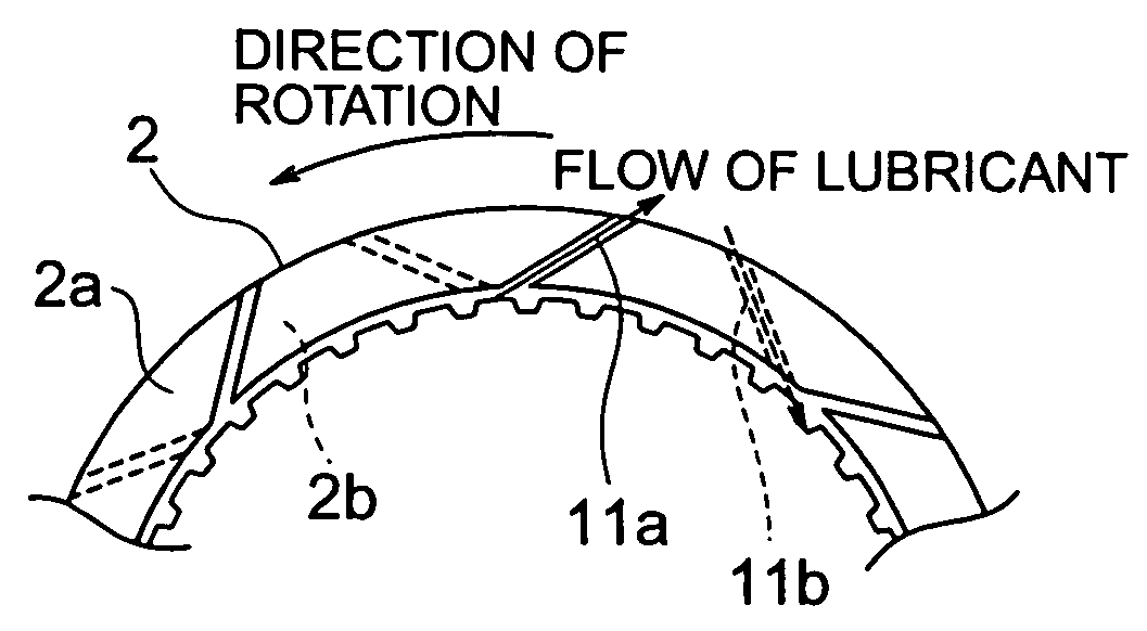
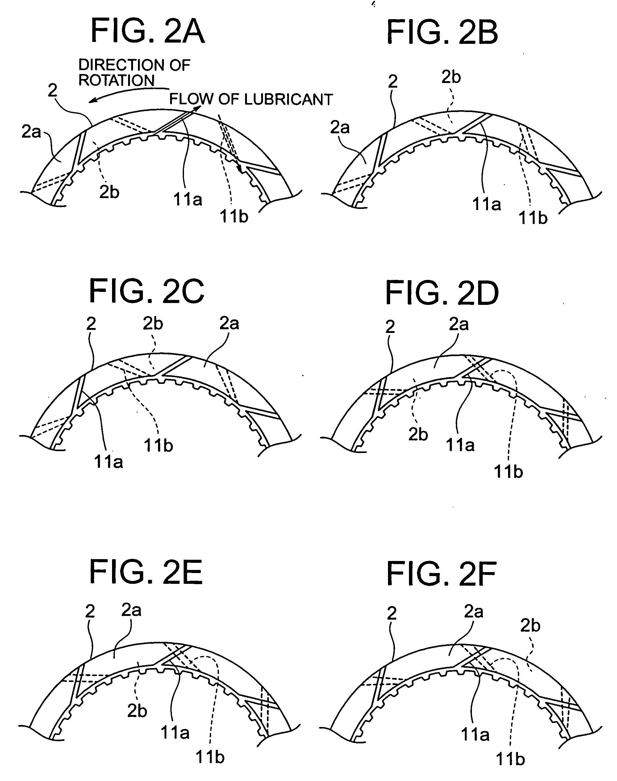
[0070]FIGS. 2A to 2F are respectively partial cut-away schematic views of a drive plate which is disposed in a multiple disc friction clutch apparatus according to the present invention.

[0071]FIG. 3A is a partial cross-sectional view of a multiple disc friction clutch apparatus according to the first embodiment of the present invention, and FIG. 3B is an enlarged cross-sectional view of an essential portion of the apparatus shown in FIG. 3A.

[0072] In the present embodiment, as shown in FIG. 2A, a friction material layer which is fixed to one side surface or front side) of the drive plate 2 is formed with a discharge groove 11a which has an inclination against the direction of rotation from the inner peripheral side toward the outer peripheral side, for discharging lubricating oil from the inner peripheral side to the outer peripheral side. Also, another friction material layer fixed to the other side(rear side) surface of the drive plate 2 is formed with an inflow groove 11b which ...

second embodiment

[0094] A wet clutch friction plate and a multiple disc friction clutch apparatus according to the present invention will be described below with reference to the drawings.

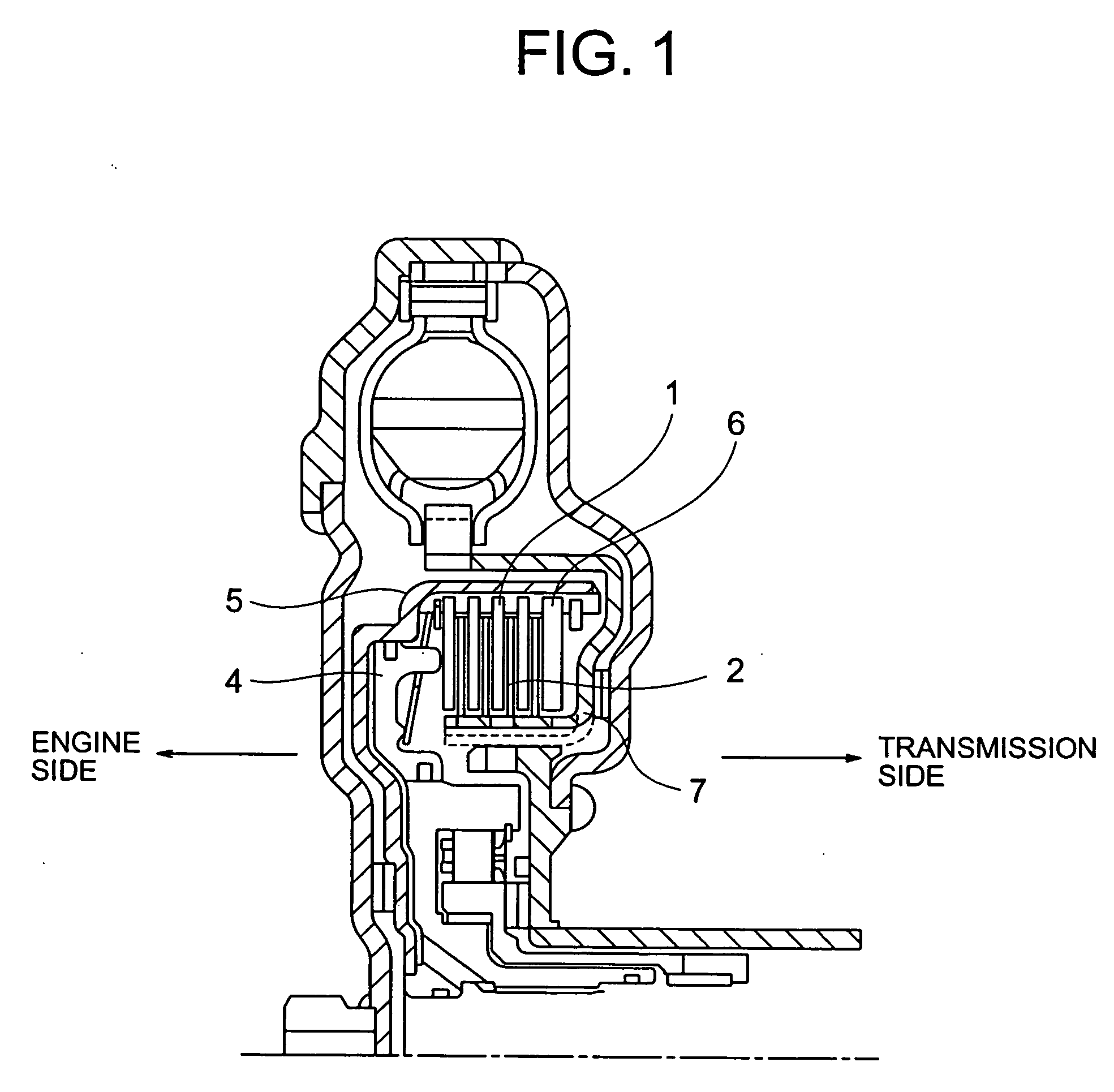
[0095]FIG. 7 is a schematic cross-sectional view of a starting clutch unit which is provided with a multiple disc friction clutch apparatus according to the second embodiment of the present invention. The starting clutch unit is connected between the engine and the transmission.

[0096] In the multiple disc friction clutch apparatus, a several number of driven plates 101 (SPs) and drive plates 102 (FPs) are provided to be alternately arranged each other in an annular chamber which is formed between a clutch drum 105 connected to the transmission side and a clutch hub 107 connected to the engine side. The driven plate 101 is a metallic plate having a spline on the outer periphery thereof, which is engaged with an inner peripheral spline of the clutch drum 105 slidably in the axial direction, while the drive plate 102...


PUM


Abstract

A wet clutch friction plate comprises a metal plate connected to a driving side, friction material layer(s) fixed to one or both side surface(s) thereof. A discharge groove is formed on one of the friction material layers and has an inclination against the direction of rotation from the inner peripheral side toward the outer peripheral side, for discharging lubricating oil from the inner peripheral side to the outer peripheral side, and an inflow groove is formed on the same or other friction material layer to face the discharge groove to receive the lubricating oil from the outer peripheral side to the inner peripheral side. A multiple disc friction clutch apparatus fastened or released by an action of a piston, comprises a clutch drum, a clutch hub, driven plates spline-fitted on the clutch drum, and drive plates spline-fitted on the clutch hub, the drive plate being the wet clutch friction plate.

Description

[0001] This application claims the benefit of Japanese Patent applications No. 2005-188869, No. 2005-188874, No. 2006-166538 and No. 2006-166544 which are hereby incorporated by reference. BACKGROUND OF THE INVENTION [0002] 1. Field of the Invention [0003] The present invention relates to a wet clutch friction plate and a multiple disc friction clutch apparatus for prolonging the life of a clutch by effectively cooling the clutch with a small flow amount of lubricating oil when a clutch is fastened in a sliding state and in a process of torque transmission and also for expanding an environment for use of the clutch. [0004] 2. Related Background Art [0005] A multiple disc friction clutch apparatus which is used in a starting clutch or a dual clutch transmission (DCT) is arranged to have a plurality of driven plates (SPs) and drive plates (FPs) which are alternately arranged on each other so as to be fastened or released in an action mode or a non-action mode in response to a pressing...

Claims


Application Information

Patent Timeline
Patent Type & Authority Applications(United States)
IPC IPC(8): F16D13/62
CPCF16D13/648F16D2069/004F16D25/123F16D25/0638
Inventor MIYAZAKI, TOMOYUKI
Owner NSK WARNER
Features
  • Generate Ideas
  • Intellectual Property
  • Life Sciences
  • Materials
  • Tech Scout
  • Unparalleled Data Quality
  • Higher Quality Content
  • 60% Fewer Hallucinations
Learn More