
Bill handling machine

a technology of a bill handling machine and a handle is applied in the field of bill handling machines, which can solve the problem of insufficient compactness of the machine, and achieve the effect of improving operability

Active Publication Date: 2007-01-04
HITACHI CHANNEL SOLUTIONS CORP
View PDF5 Cites 21 Cited by
  • Summary
  • Abstract
  • Description
  • Claims
  • Application Information

AI Technical Summary

Benefits of technology

[0008] An object of the present invention is to provide a bill handling machine which can make the machine further compact, while paying attention particularly to the money input and output port and the temporary storage portion.
[0009] Further, an object of the present invention is to provide the machine having an excellent operability with respect to taking out the bill in the money input and output port.
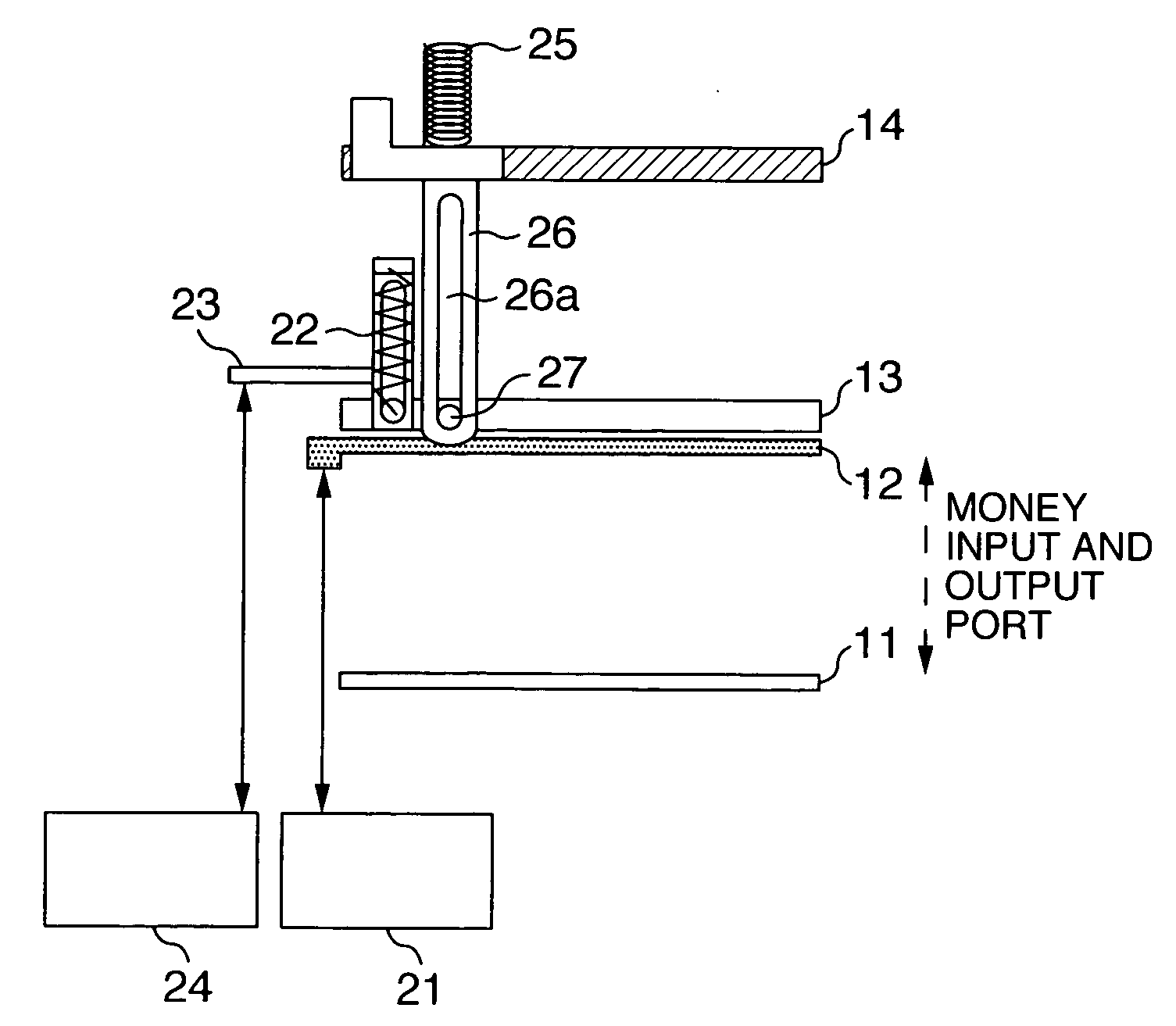
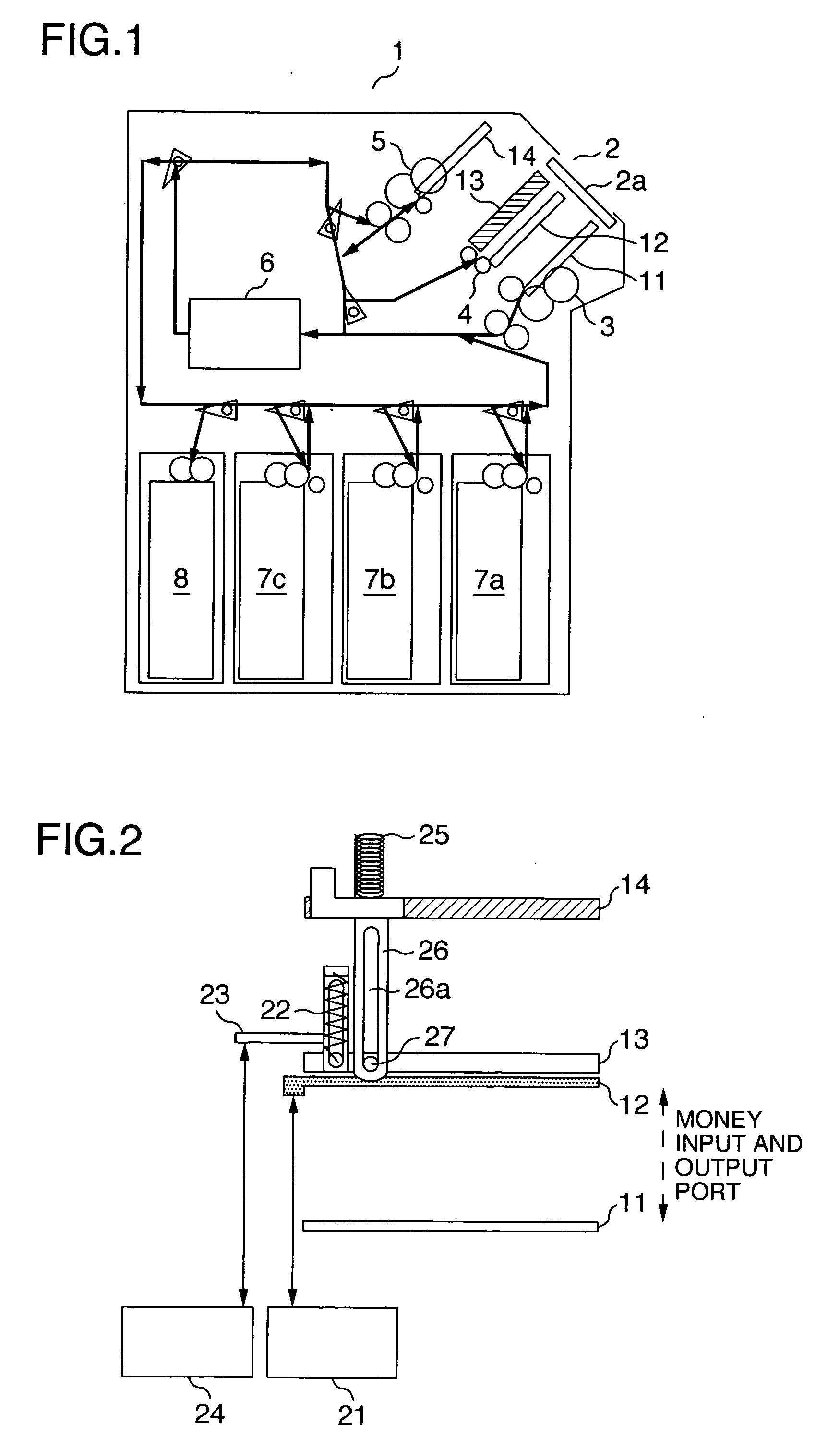
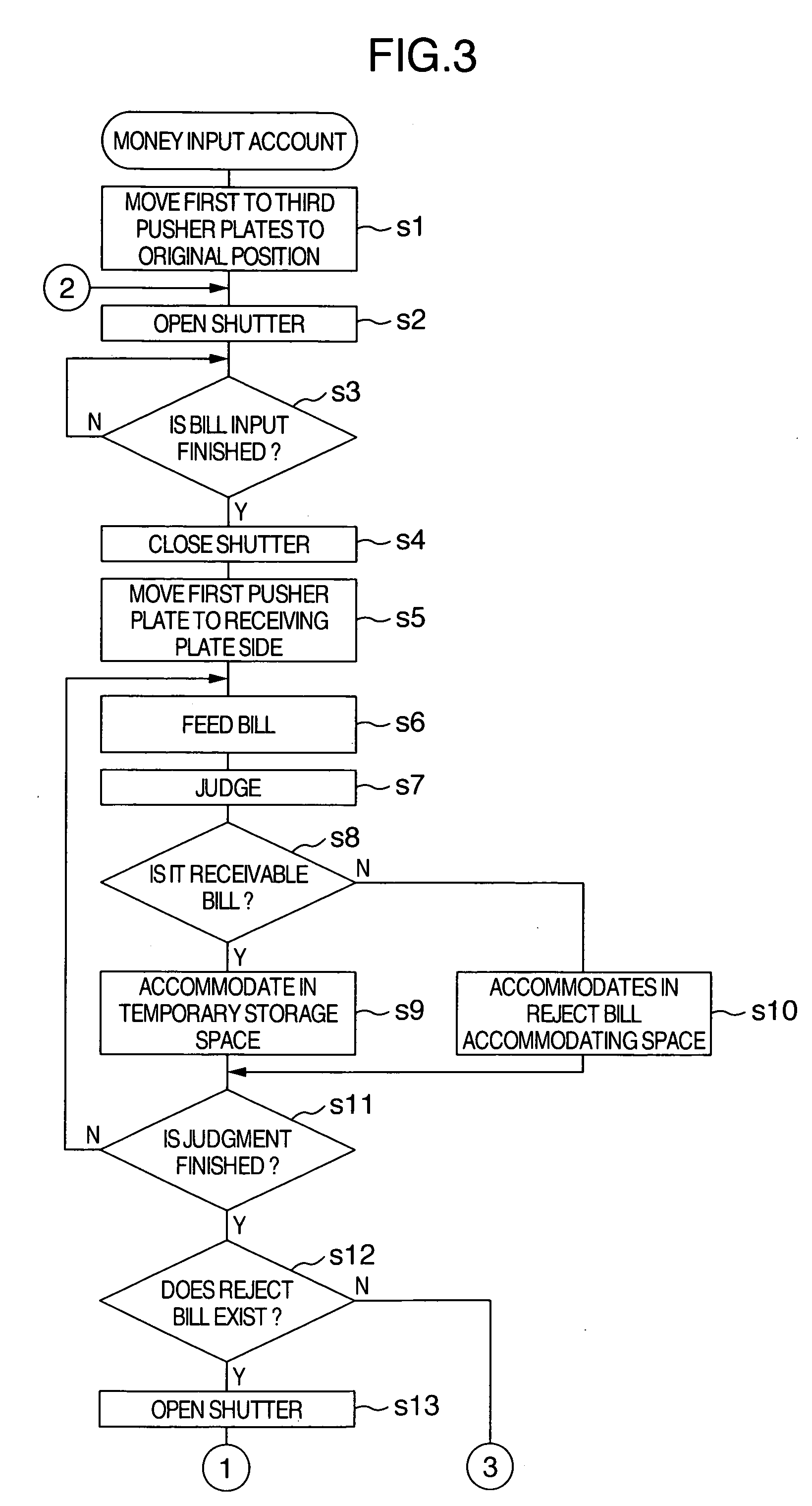
[0011] Since it is possible to adjust a space facing to the money input and output port by divisionally forming first to third bill accommodating spaces comprising an input bill putting space at a time of the money input account, a reject bill accommodating space accommodating the reject bill and a temporary storage space accommodating the received bill, moving three pusher plates (pressure plates or push plates) and adjusting positions of the pusher plates, it is possible to make the machine main body compact.
[0012] Further, it is possible to achieve a security property and an improved operability on the basis of a shape of the pusher plates forming the temporary storage portion.

Problems solved by technology

However, in the bill handling machine shown in the patent document 1, since it is necessary to form a temporary storage portion temporarily storing the bill judged as a receivable bill at a time of the money input account until the user confirms the input money amount separately from the input and output bill accommodating space and in an isolating manner within the machine, the machine is not made sufficiently compact.

Method used


Image

  • Bill handling machine
  • Bill handling machine
  • Bill handling machine

Examples


Embodiment Construction

[0029] A description will be given below of a bill handling machine in accordance an embodiment of the present invention. FIG. 1 shows an outline cross sectional view of a structure of a main portion of a bill handling machine. A bill handling machine 1 has a function that a money input account and a money output account execute by a control portion controlling an entire of the machine, and is called as an automatic teller machine (ATM) together with a card mechanism portion handling a card, an operation portion operated by a customer and the like. A money input and output port 2 for the bill is formed in a front face of the main body. A shutter 2a is provided in the money input and output port 2. A receiving plate 11, a first pusher plate 12 (which may be called as a plate simply, and so on), a second pusher plate 13 and a third pusher plate 14 are provided in a rising manner in an inner side of the machine facing to the money input and output port 2 in this order from a lower end ...


PUM


Abstract

An object of the invention is to provide a bill handling machine in which a machine main body is made compact by moving a plate as occasion demands so as to adjust a space facing to a money input and output port, and a temporary storage portion temporarily storing a bill in a money input account is arranged near a first accommodating portion for the input bill sectionalized by the plate, in the bill handling machine.

Description

INCORPORATION BY REFERENCE [0001] The present application claims priority from Japanese application JP 2005-174492 filed on Jun. 15, 2005, the content of which is hereby incorporated by reference into this application. BACKGROUND OF THE INVENTION [0002] 1. Field of the Invention [0003] The present invention relates to a bill handling machine which executes a money input account receiving a bill put in the machine and a money output account discharging the bill accommodated in the machine. [0004] 2. Description of Related Art [0005] The bill handling machine such as an automatic teller machine (ATM), a cash dispenser (CD) or the like executing the money input account and the money output account is installed in a shop such as a financial institution, a convenience store or the like. The bill handling machine is structured such that an input and output bill accommodating space for accommodating the bill (the input and output bill) for the money input account and the money output accou...

Claims


Application Information

Patent Timeline
IPC IPC(8): B07C5/00
CPCG07D11/0018G07F19/205G07F19/20G07D11/14G07D2211/00G07F19/201
Inventor NAGURA, AKIHIRO
Owner HITACHI CHANNEL SOLUTIONS CORP
Learn More