Webcam clip

a webcam and clip technology, applied in the field of webcam clips, can solve the problems of inability to meet the requirements of webcams available now, thin thickness of panels, and difficulty in firmly mounting webcams with adjustable lenses on the panels, etc., to achieve convenient lens adjustment, easy assembly, and easy setup

Inactive Publication Date: 2007-01-04
E PIN INT
View PDF5 Cites 56 Cited by
  • Summary
  • Abstract
  • Description
  • Claims
  • Application Information

AI Technical Summary

Benefits of technology

[0002] Therefore it is a primary object of the present invention to provide a webcam clip that uses a bent metal to form a U-shaped frame with a clipping part and a pivoting part. The clipping part makes the present invention easily clip on edges of panels while the pivoting part formed by two ends of the U-shaped frame. The pivoting part can be disposed on a first concave hole arranged symmetrically on right and left sides of a housing of webcam so as to form a pivot between the U-shaped frame and the housing. Therefore, the angles of lens are adjustable. The webcam is not only easy to set up but also convenient for adjusting lens.
[0003] It is another object of the present invention to provide a webcam clip that having a guiding slot connecting a first concave hole on a housing of the webcam and a second concave hole so as to make the pivoting part of the clip elastically move from the first concave hole to

Problems solved by technology

However, the thickness of the panels is thin.
Thus it is difficult to set up the webcam with ad

Method used


Image

  • Webcam clip
  • Webcam clip
  • Webcam clip

Examples


Embodiment Construction

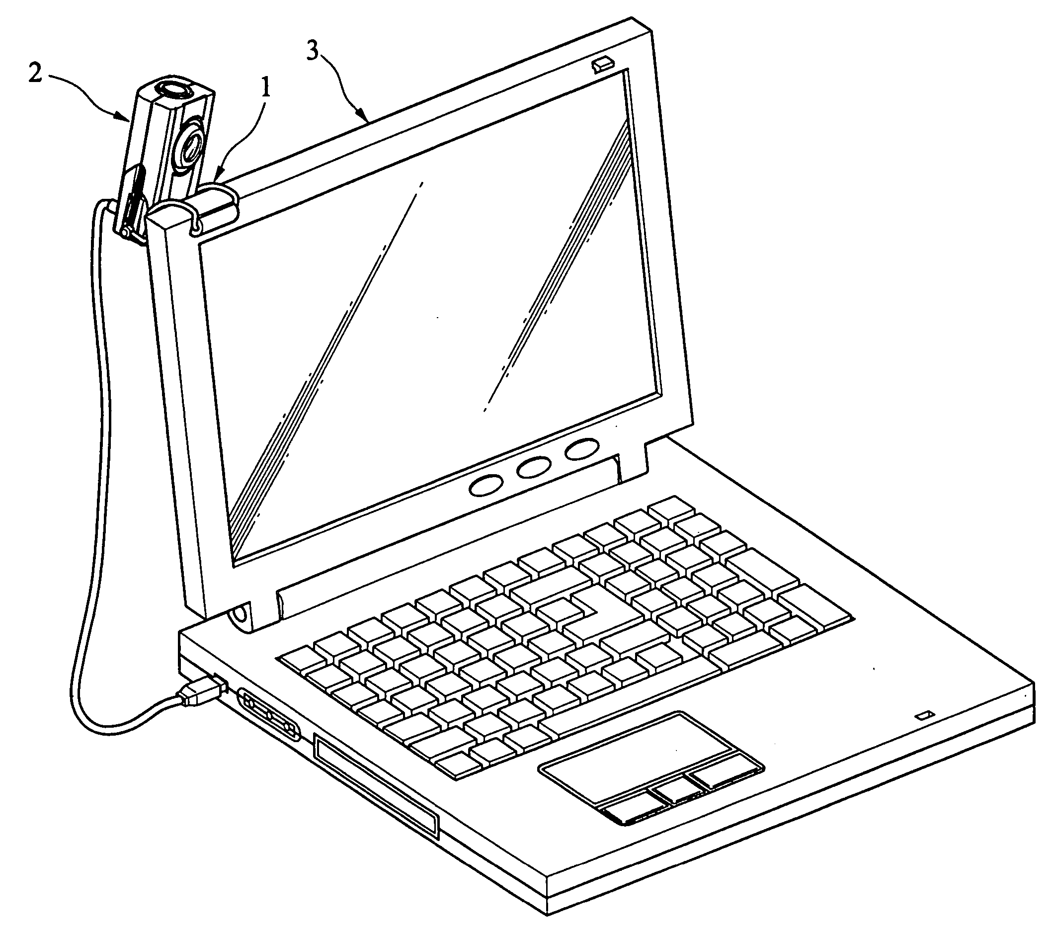
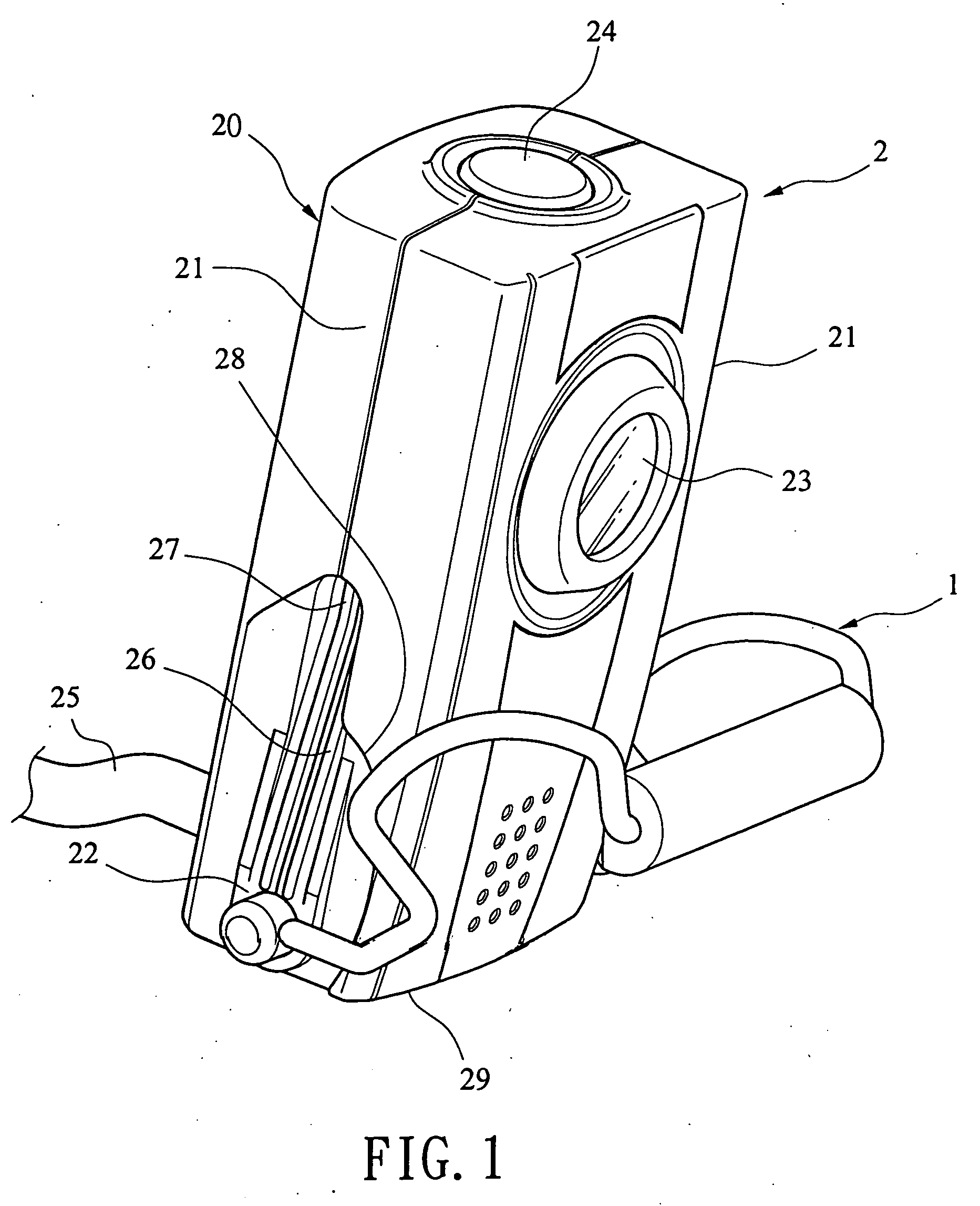
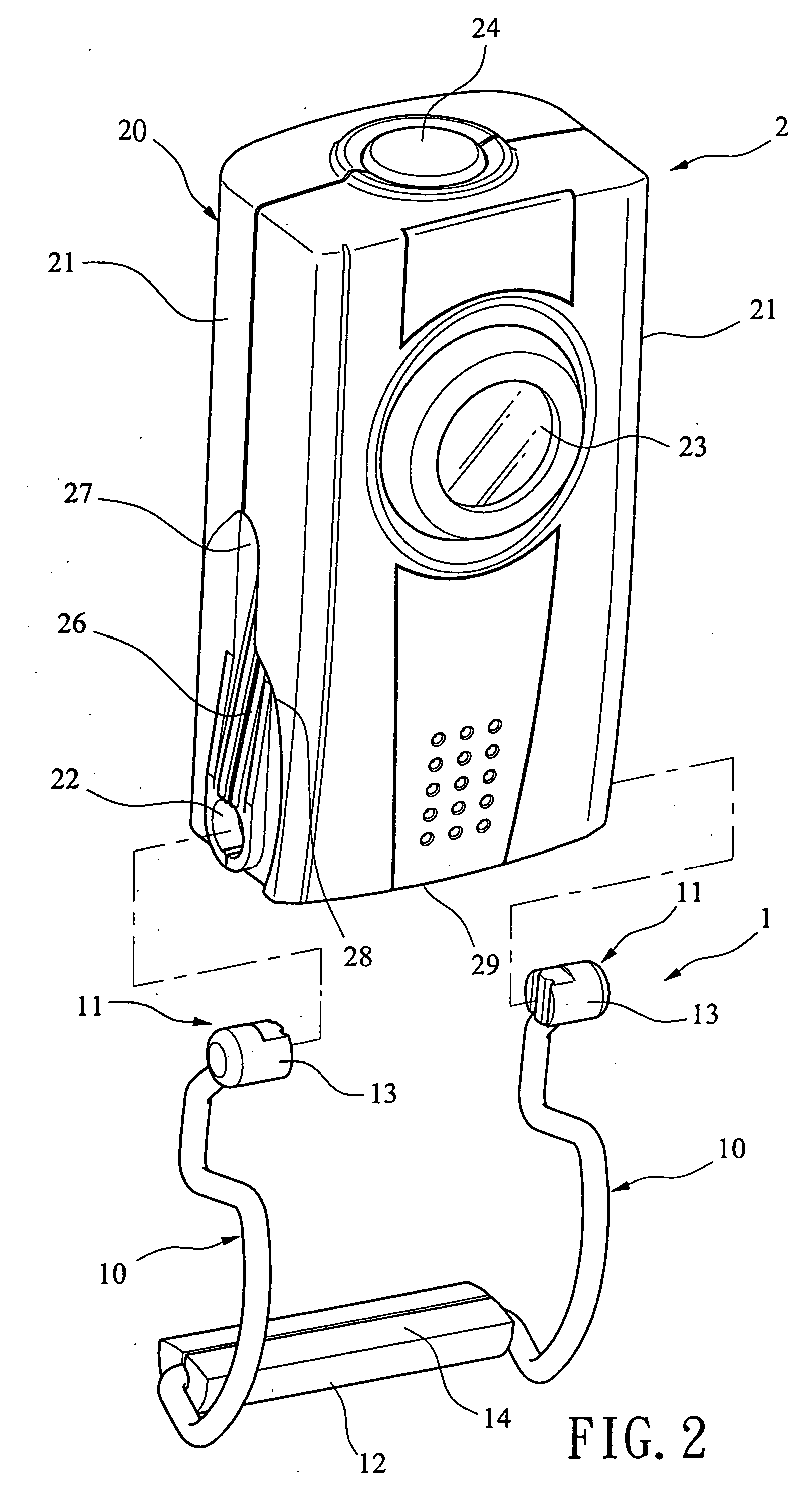
[0014] Refer to FIG. 1, FIG. 2&FIG. 3, a webcam clip 1 in accordance with the present invention is used in combination with a webcam 2. A clip 1 is a U-shaped frame that is formed by bending a metal wire with certain wire diameter. The clip 1 consists of a clipping part 10 and a pivoting part 11. The clipping part 10 is symmetrically disposed on right and left sides of the U-shaped frame. The width of the clipping part 10 fits the thickness of a panel 31 of a computer 3 so that the clip 1 is installed on edges of the panel 31 by the clipping part 10, as shown in FIG. 4, FIG. 5, &FIG. 5A. Moreover, the pivoting part 11 is symmetrically arranged on two ends of the left and right sides of the metal U-shaped frame. When being used, the pivoting part 11 is clipped on a first concave hole 22 positioned symmetrically in left and right sides 21 of a housing 20 of the webcam 2 so as to form a pivot between the U-shaped clip 1 and the webcam 2. Therefore, shooting angle of lens 23 of the webc...


PUM


Abstract

A webcam clip is disclosed. The webcam is a U-shaped frame with a clipping part and a pivoting part formed by bent metal wire with certain wire diameter. The clipping part makes the present invention easily clip on edges of panels while the pivoting part is formed by two rear ends of the U-shaped frame for being disposed on a first concave hole arranged symmetrically on right and left sides of a housing of webcam so as to form a pivot between the U-shaped frame and the housing. Therefore, the angles of lens are adjustable. Moreover, a guiding slot is arranged above the first concave hole for connecting the first concave hole with a second concave hole so as to make the pivoting part of the clip elastically move from the first concave hole to the second concave hole along the guiding slot and the device is in folded form. Or the pivoting part can move in reverse direction, from the second concave hole to the first concave hole, along the guiding slot for being used. Thus the clip for webcam has simplified structure that is easy to be used or stored. With compact design, the storage space is saved and the device is easy to carry.

Description

BACKGROUND OF THE INVENTION [0001] The present invention relates to a webcam clip, especially to a webcam clip clipped on a housing of webcam so as to adjust angles of lens and easily set up, or carry the webcam. Due to popularity of internet communication, the network camera (also called webcam, or PC camera) has become a common equipment for users. Most of people set the webcam above the monitor or LCD (liquid crystal display) panels of computers so as to make the lens face users. However, the thickness of the panels is thin. For example, the thickness of ASUS notebooks ranges from 8 mm to 14 mm. Thus it is difficult to set up the webcam with adjustable lens firmly on the panel. Especially notebooks are portable so that the webcam also need to have features with portability, compact, convenient set-u, and easy adjustment. But the webcam available now can't match above requirements. SUMMARY OF THE INVENTION [0002] Therefore it is a primary object of the present invention to provide...

Claims


Application Information

Patent Timeline
IPC IPC(8): A47G29/00F16M11/00
CPCF16M13/02G06F1/1607F16M13/022F16M13/005F16M11/10
Inventor SHYU, SAN-WUEIHUANG, SHIH-CHAOCHU, HSIEN-RU
Owner E PIN INT
Why Eureka
Try Eureka