
Cutting board and stand

Inactive Publication Date: 2007-01-04
THE COLMAN GRP INC
View PDF28 Cites 60 Cited by
  • Summary
  • Abstract
  • Description
  • Claims
  • Application Information

AI Technical Summary

Benefits of technology

[0008] In one preferred embodiment, the present invention comprises one or more cutting boards mounted on a stand. The cutting board(s) are thus, raised off the counter or other work surface. This accomplishes a number of things. First, it places the cutting board at a more comfortable height for cutting while bringing the work surface closer to the user's eyes for greater visual acuity. Second, it permits the placement of one or more pans in or beneath the cutting board(s) to catch scraps or juice or hold sauces or other accompaniments for service. Third, it permits full pans of scrap or juice to be removed without having to displace the cutting board. And fourth, it helps avoid contamination with other things that may also be on the counter.
[0009] Preferably, the cutting boards of the present invention have a hole therein through which waste materials can be dropped. When the cutting board is supported on a stand that lifts the cutting board off the work surface, waste materials can be pushed through the hole directly into a catch pan mounted in or below the cutting board. Alternatively, the cutting board, with or without a supporting device, can be extended over the end of the counter, placed on a trash receptacle or extended over a sink having a garbage disposal so as to make disposal of scrap juice and materials through the hole even simpler.

Problems solved by technology

This can be difficult where counter space as it a premium and significant preparation involving cutting needs to be undertaken.
Limited space increases the risk of cross contamination where, for example, poultry and vegetables are both being cut on contiguous or substantially contiguous surfaces.
Often, when cutting is done, scrap is created.
Where the scrap is piled up on the cutting board, the space necessary to cut is diminished and the possibility of the scrap becoming intermingled with the material to be used is quite high.
Where the scrap is thrown into a nearby trash receptacle, floor space may be compromised by having to station the receptacle nearby and additional handling of scrap material is required that could increase the risk of sanitation issues.
When the object being cut is juicy, the risks increase still further.
Juices can run randomly off the cutting board onto the counter and the floor creating numerous hazardous conditions.
This creates the possibility of back injuries, makes it more difficult to see what is being cut and contributes to a more hazardous and less ergonomic work environment.
As can be seen, current cutting boards suffer from certain drawbacks and limitations.

Method used


Image

  • Cutting board and stand
  • Cutting board and stand
  • Cutting board and stand

Examples


Embodiment Construction

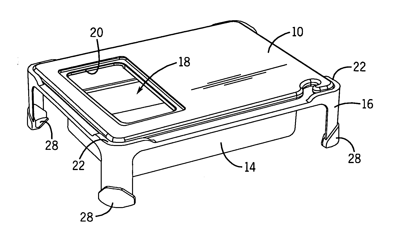
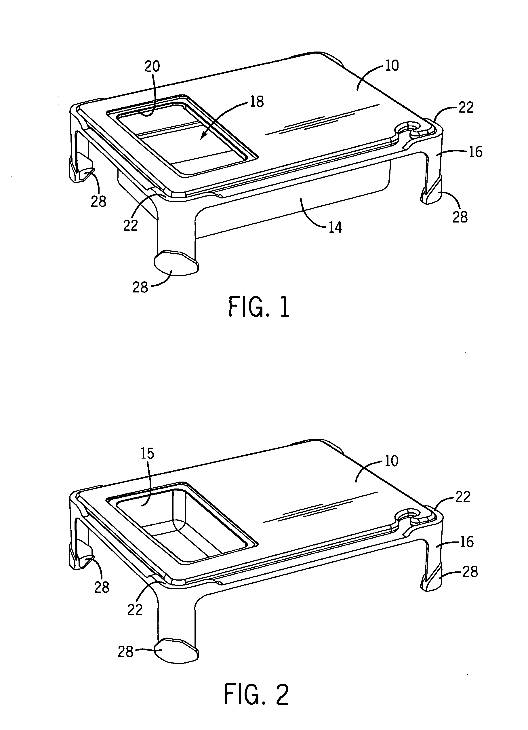
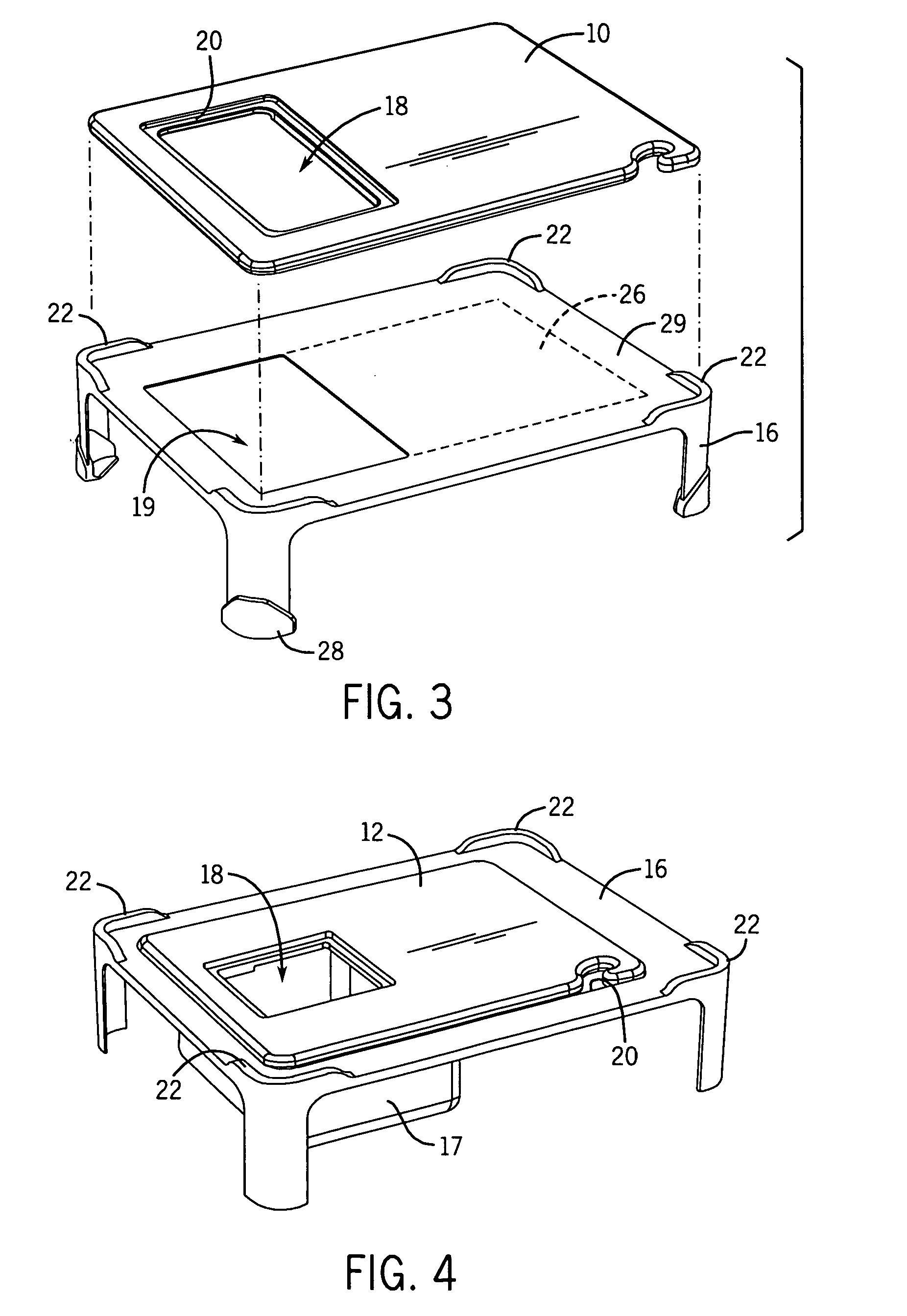
[0025] As shown in FIGS. 1-13, various embodiments of the present invention comprise one or more cutting boards 10 and 12, a pan 14, 15 or 17 and a stand 16. Preferably each cutting board 10, 12 has a hole 18 that corresponds, at least in part, to a hole or cutout 19 in the stand 16. However, since the cutting boards of the present invention can be used without the stand 16, the hole 18 can be made any size that permits juices and / or cutting scraps to be moved therethrough.

[0026] Preferably the hole in each cutting board has a recessed lip 20 to accommodate the insertion of one or more pans 15. When a pan 15 is placed in the hole, the pan's peripheral edge 15 engages the recessed lip 20 of the cutting board such that the pan's peripheral edge is even with or below the top surface of the cutting board to facilitate the transfer of juices and or cutting scraps into the pan 15.

[0027] As shown in FIG. 12, the cutting boards 10 and 12 of the present invention may also include at least ...


PUM


Abstract

A device for preparing food includes a stand having a plurality of legs for supporting at least one cutting board and lifting it off a work surface. The cutting board has a hole in it. A pan fits in or underneath the hole to catch juices, scraps or finished cut items cut on the cutting board.

Description

CROSS-REFERENCE TO RELATED APPLICATIONS [0001] This application claims priority under 35 U.S.C. § 119 (e) to U.S. Provisional Application Ser. No. 60 / 683,456, filed May 20, 2005.FIELD OF THE INVENTION [0002] This invention relates generally to food preparation and more particularly to cutting boards used in the preparation of food. BACKGROUND OF THE INVENTION [0003] In commercial kitchens, maintaining sanitary conditions is of critical importance. This can be difficult where counter space as it a premium and significant preparation involving cutting needs to be undertaken. Limited space increases the risk of cross contamination where, for example, poultry and vegetables are both being cut on contiguous or substantially contiguous surfaces. Generally, thick plastic cutting boards are employed that raise the cutting surface off the counter on which the cutting boards are placed from about ¼ of an inch to about ¾ of an inch. This minimal height difference makes it more likely than not ...

Claims


Application Information

Patent Timeline
IPC IPC(8): B23Q3/00
CPCA47J47/005
Inventor PEARL, JAYSONYOUNG, MICHAELOMDOLL, PAUL A.FAIOLA, NORM
Owner THE COLMAN GRP INC
Learn More