Intake gasket

Inactive Publication Date: 2007-01-04
NICHIAS CORP
View PDF23 Cites 16 Cited by
  • Summary
  • Abstract
  • Description
  • Claims
  • Application Information

AI Technical Summary

Benefits of technology

[0011] In the intake gasket of the present invention, a space is formed from the rib of the intermediate rib member and the metal plates disposed on both sides of the intermediate rib member, and air is accumulated in that space. The coefficient of thermal conductivity of the air at a standard atmospheric pressure is 0.1-0.01 W/mK, which is smaller by two digits or more

Problems solved by technology

For this reason, the air layer entrapped in the space between the metal plates can shut out heat from the cylinder head and make transmi

Method used


Image

  • Intake gasket
  • Intake gasket
  • Intake gasket

Examples


example 1

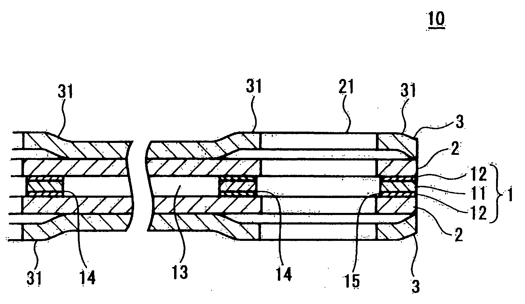
[0031] The following intermediate rib member, metal plate, and elastic metal substrate were prepared. The intermediate rib member was sandwiched between the two metal plates. This intermediate rib member sandwiched between the two metal plates was further sandwiched between the two elastic metal substrates. The entire object was clamped to obtain an integral laminated body A. Using the resulting laminated body, the temperature difference between the cylinder head and intake manifold was measured by the method described below. As a result, when the thickness of the air layer was 0.4 mm, the temperature difference between the cylinder head and intake manifold was 13° C.

(Preparation of Intermediate Rib Member)

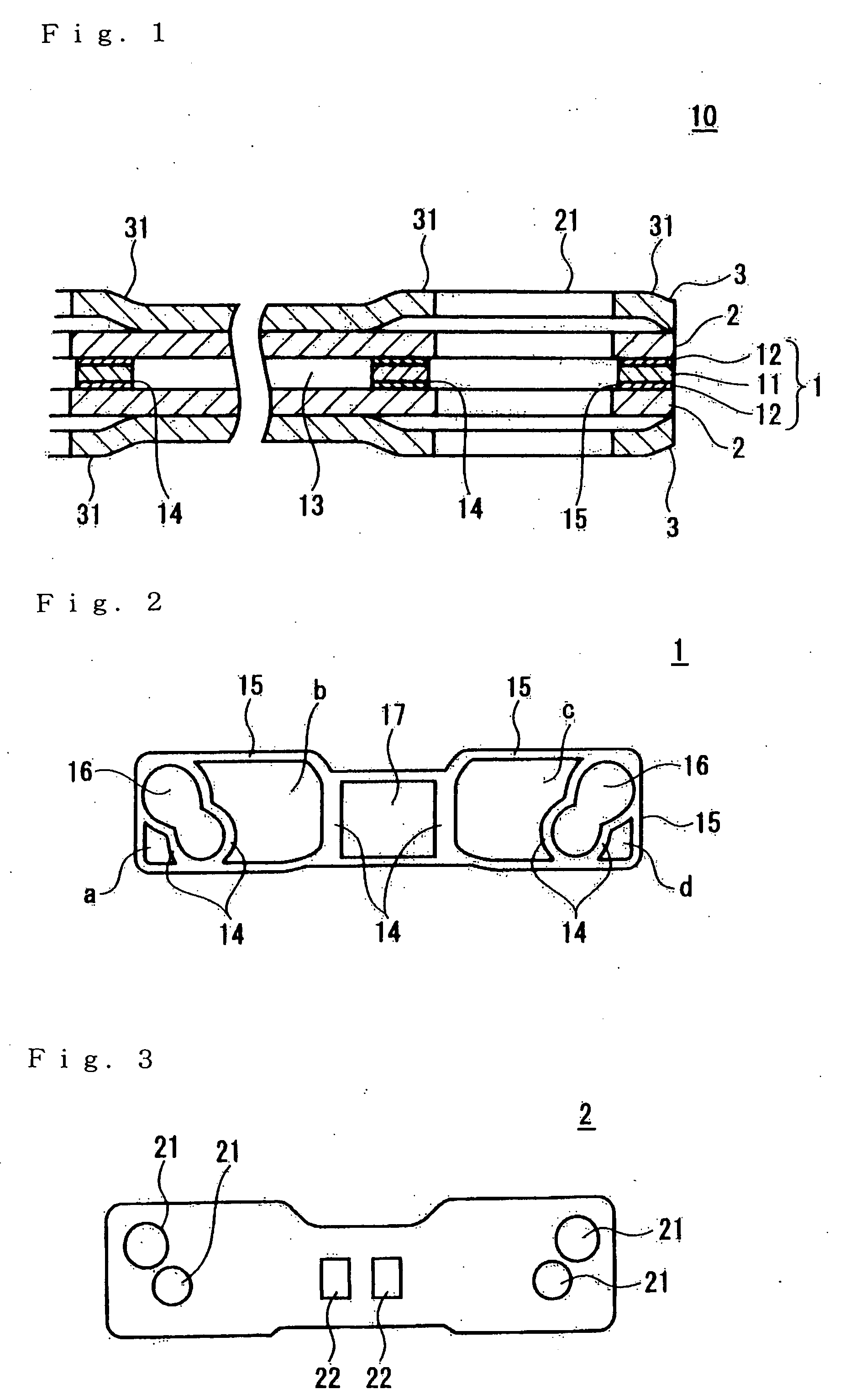
[0032] A foamed rubber layer with a thickness of 200 μm was applied to both sides of a steel plate (SPCC) with a thickness of 0.2 mm by the method described below, and cut into a formed object corresponding to that shown in FIG. 2.

(Method for Forming Foamed Rubber Layer)

[003...

example 2

[0037] An intermediate rib member was obtained according to the same method as in Example 1, except that the foamed rubber layer with a thickness of 200 μm was formed on both sides of a steel plate (SPCC) with a thickness of 1.0 mm by the method described below and an air layer with a thickness of 1.2 mm was provided. A laminated body B was prepared in the same manner as in Example 1, except for using this intermediate rib member. As a result, when the thickness of the air layer was 1.2 mm, the temperature difference between the cylinder head and intake manifold was 16° C.


PUM


Abstract

An intake gasket to be inserted between a cylinder head and a manifold, comprising an intermediate rib member 1 with a three-layer structure formed from a thin metal plate 11 and rubber layers 12 and 12 provided on both sides of the thin metal plate, metal plates 2 and 2 disposed on both sides of the intermediate rib member 1, and elastic metal substrates 3 and 3 disposed on both sides of the metal plates 2 and 2, the intermediate rib member 1 comprising a first rib 15 formed around the periphery thereof and a second rib 14 formed around the periphery of a fluid passage hole, wherein a space is formed from the rib of the intermediate rib member 1 and the metal plates 2 and 2 disposed on both sides of the intermediate rib member 1. The intake gasket can shut out heat from the cylinder head so as to make transmission of heat to the manifold difficult.

Description

BACKGROUND OF THE INVENTION [0001] 1. Field of the Invention [0002] The present invention relates to an intake gasket to be inserted between a cylinder head and a manifold so as to inhibit a temperature increase in an intake manifold. [0003] 2. Background Art [0004] A gasket for the manifold of the intake air converging section (intake manifold) in conventional engines is a laminated body of metal plates having a bead formed around the periphery of intake holes (such a gasket being herein referred to as “intake gasket”). The intake gasket is placed between a cylinder head and a manifold. Heat of the cylinder head is transmitted to the manifold via the gasket, thereby increasing the temperature of the manifold. As a result, the temperature of the manifold increases close to the temperature of the cylinder head. [0005] The intake-air temperature must be reduced for increasing the engine output. Because the intake air is sent to the cylinder head via the manifold, the temperature of th...

Claims


Application Information

Patent Timeline
IPC IPC(8): F02F11/00
CPCF02F11/002
Inventor WATANABE, KATSUMIHAYASHI, YUICHI
Owner NICHIAS CORP
Why Eureka
Try Eureka