Electric motor

a technology of electric motors and motors, applied in the direction of magnetic circuit rotating parts, magnetic circuit shapes/forms/construction, windings, etc., can solve the problems of generating short circuit between the terminal and the bracket, unable to completely insulate the circuit board from the bracket, and the mold cannot be closed smoothly, so as to reduce manpower and reduce the effect of time and high accuracy

Active Publication Date: 2007-01-04
FUJITSU GENERAL LTD
View PDF11 Cites 17 Cited by
  • Summary
  • Abstract
  • Description
  • Claims
  • Application Information

AI Technical Summary

Benefits of technology

[0007] The present invention has been made to solve the above-mentioned problems, and accordingly an object thereof is to provide an electric motor that requires reduced manpower for assembling a stator and is capable of being assembled with high accuracy in a shorter period of time.
[0011] According to this configuration, since the second concave portion is provided on the side surface side of the terminal pin, a wide insulation space can be provided between the terminal pin and the inner peripheral surface, so that a short circuit etc. can be prevented.
[0013] According to this configuration, since the first and second concave portions have the same diameter, a mold for insert molding can be designed more easily.
[0015] According to this configuration, since the diameter of the second concave portion is preferably larger than the diameter of the first concave portion, a wide insulation space can be provided, so that the danger of short circuit can further be reduced.
[0017] According to this configuration, since the diameter of the second concave portion is determined by depending on the distance between a bracket and the terminal pin, an electric motor in which a short circuit is less liable to occur even if the distance between the bracket and the terminal pin is designed so as to be short can be provided.

Problems solved by technology

However, only the insertion of the insulating sheet described in Patent Document 1 between the circuit board and the bracket cannot completely insulate the circuit board from the bracket.
That is to say, in the case of Patent Document 1, since the insulation distance between the bracket and the terminal of the circuit board is short, there is a fear of generating a short circuit between the terminal and the bracket when a high load is applied to the motor.
However, the technique described in Patent Document 2 has a drawback in that if the initial positions are inconsistent with each other, the mold and the terminal pin come into contact with each other, so that the mold cannot be closed smoothly.
Also, if an attempt is made to forcedly fit the terminal pin, the terminal pin may be damaged.

Method used


Image

  • Electric motor
  • Electric motor
  • Electric motor

Examples


Embodiment Construction

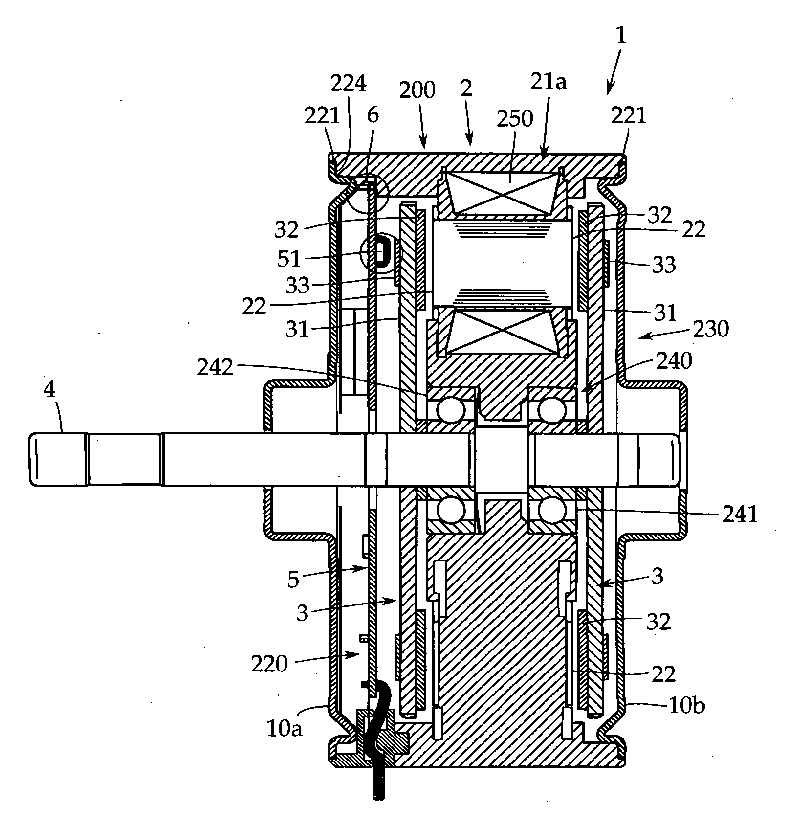
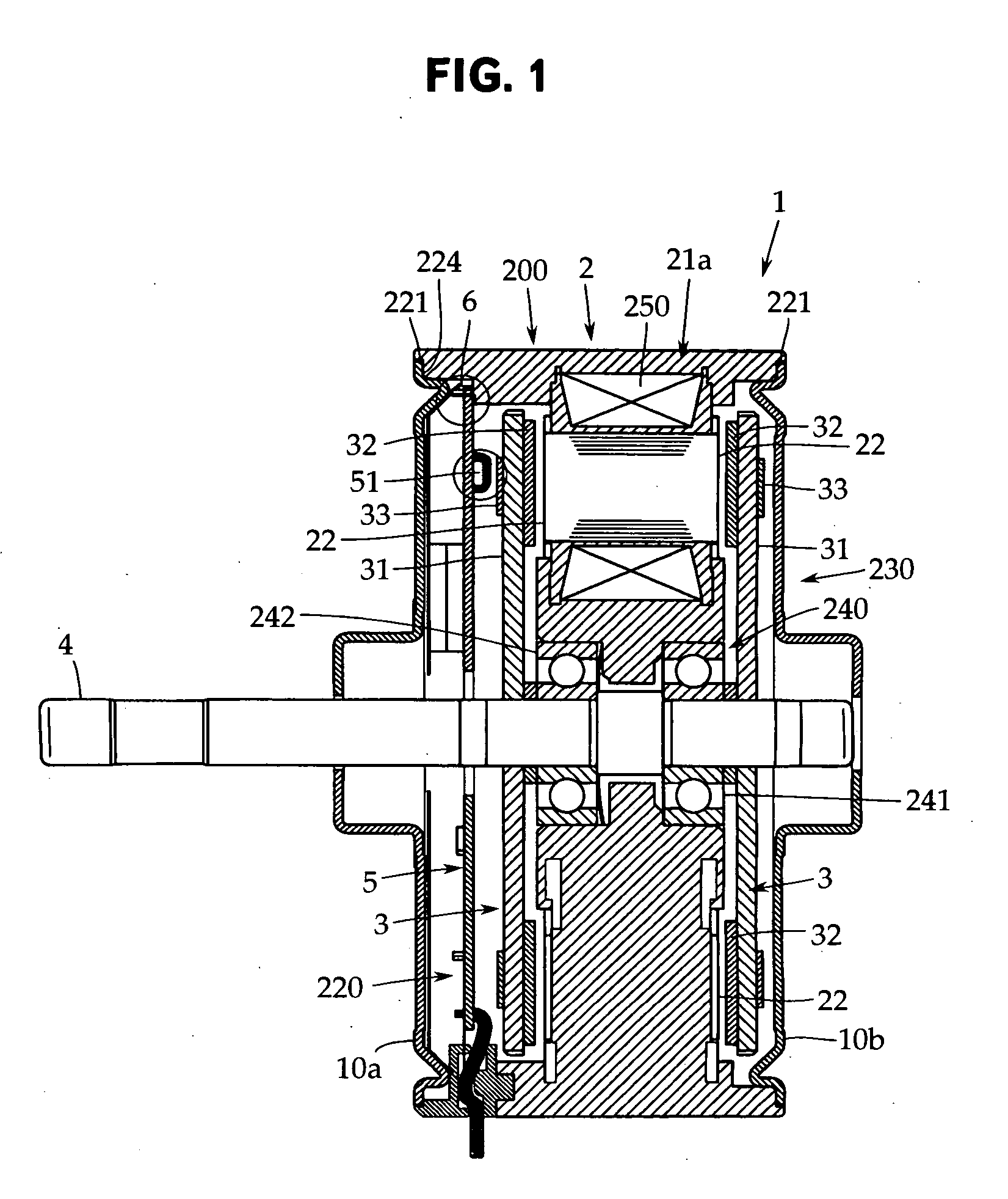
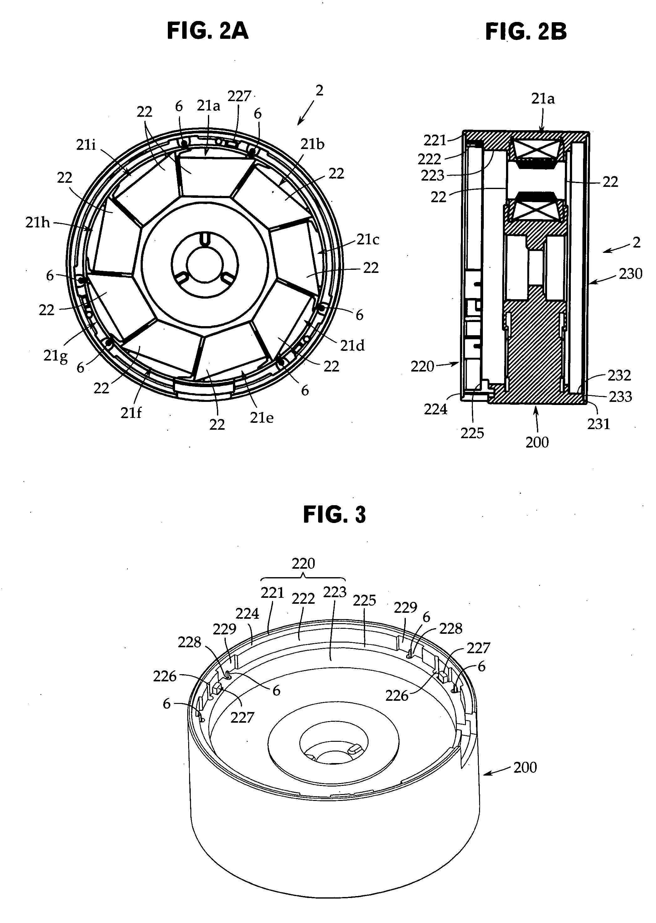
[0041] An embodiment of the present invention will now be described with reference to the accompanying drawings. The present invention is not limited to this embodiment. FIG. 1 is a sectional view of an essential portion of an axial air-gap electric motor in accordance with one embodiment of the present invention. FIGS. 2A and 2B are front and side views of a stator, respectively, and FIG. 3 is a perspective view of the stator.

[0042] This axial air-gap electric motor 1 has a stator 2 embedded in a resin compact 200 and a pair of rotors 3 arranged so as to face to both side surfaces of the stator 2 in the axial direction with a predetermined air gap being provided. The rotors 3 are fixed coaxially on a rotor output shaft 4 for delivering a rotational driving force.

[0043] The stator 2 is formed in a ring shape with the axis line of the rotor output shaft 4 being the center, and is integrally molded together with the resin compact 200 by insert molding. At both ends of the resin comp...


PUM


Abstract

There is provided an electric motor that requires reduced manpower for assembling core members and is capable of being assembled in a shorter period of time. A height difference surface 225 on which a circuit board 5 for driving control is mounted is provided between a first inner peripheral surface 222 and a second inner peripheral surface 223, the tip end of a terminal pin 6 is projected in a part of the height difference surface 225, and further a first concave portion 228 formed by recessing the surroundings of the terminal pin 6 in the axis line direction of the terminal pin is provided in the height difference surface 225.

Description

TECHNICAL FIELD [0001] The present invention relates to an electric motor having a stator embedded in a synthetic resin compact and a rotor arranged so as to face to the teeth surface of the stator. More particularly, it relates to an electric motor that requires less manpower for parts and is capable of being assembled easily in a short period of time. BACKGROUND ART [0002] As shown, for example, in Patent Document 1 (Japanese Patent Application Publication No. H05-292697), an electric motor has a stator arranged in a bracket and a rotor arranged so as to face to the teeth surface of the stator. The electric motors come in a radial gap type such as an inner rotor type in which the rotor is rotatably arranged in the center of the stator and an outer rotor type in which the rotor is arranged on the outer periphery side of the stator, and an axial air-gap type in which the disc-shaped rotor is arranged along the axis line so as to face to the side surface of the similarly disc-shaped ...

Claims


Application Information

Patent Timeline
Patent Type & Authority Applications(United States)
IPC IPC(8): H02K21/12H02K16/02
CPCH02K1/14H02K1/182H02K3/524H02K5/08H02K2211/03H02K11/0073H02K21/24H02K2203/06H02K2203/12H02K7/08H02K11/33
Inventor KOJIMA, TOMONORIMATSUZAKI, HIROKAZUYAMADA, MASAKI
Owner FUJITSU GENERAL LTD
Why Eureka
Try Eureka