Multi-band planar antenna

Inactive Publication Date: 2007-01-04
QUANTA COMPUTER INC
View PDF6 Cites 10 Cited by
  • Summary
  • Abstract
  • Description
  • Claims
  • Application Information

AI Technical Summary

Benefits of technology

[0009] Therefore, the object of the present invention is to provide a multi-band planar antenna that can overcome the aforesaid drawbacks of the prior art.

Problems solved by technology

The aforementioned conventional planar antenna 1 is disadvantageous in that, based from experimental results, as illustrated in FIG. 3, the conventional planar antenna 1 provides a relatively high voltage standing wave ratio (VSWR), i.e., greater than three, within the DCS 1800 and PCS 1900 frequency bandwidths.

Method used


Image

  • Multi-band planar antenna
  • Multi-band planar antenna
  • Multi-band planar antenna

Examples


Embodiment Construction

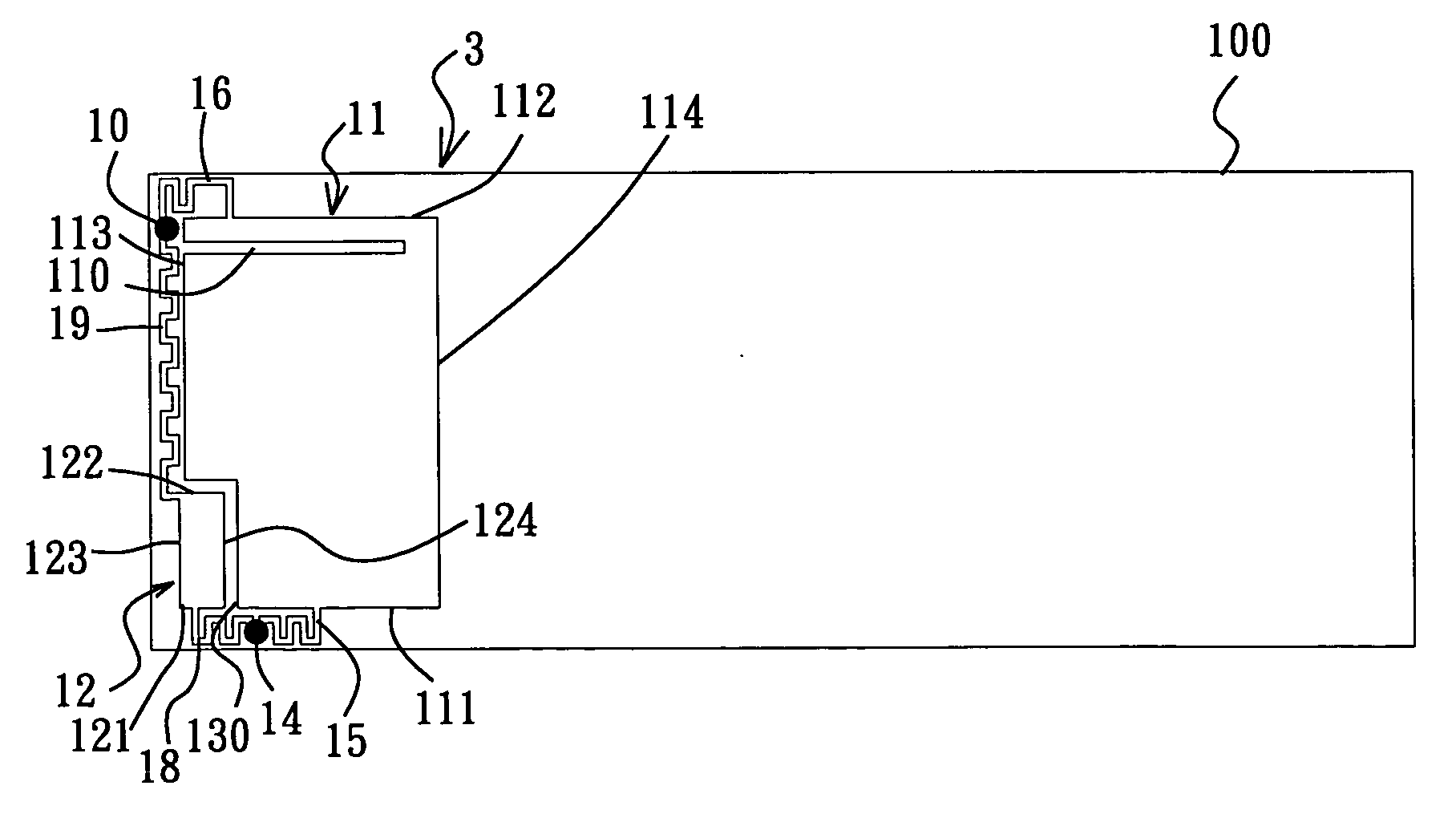
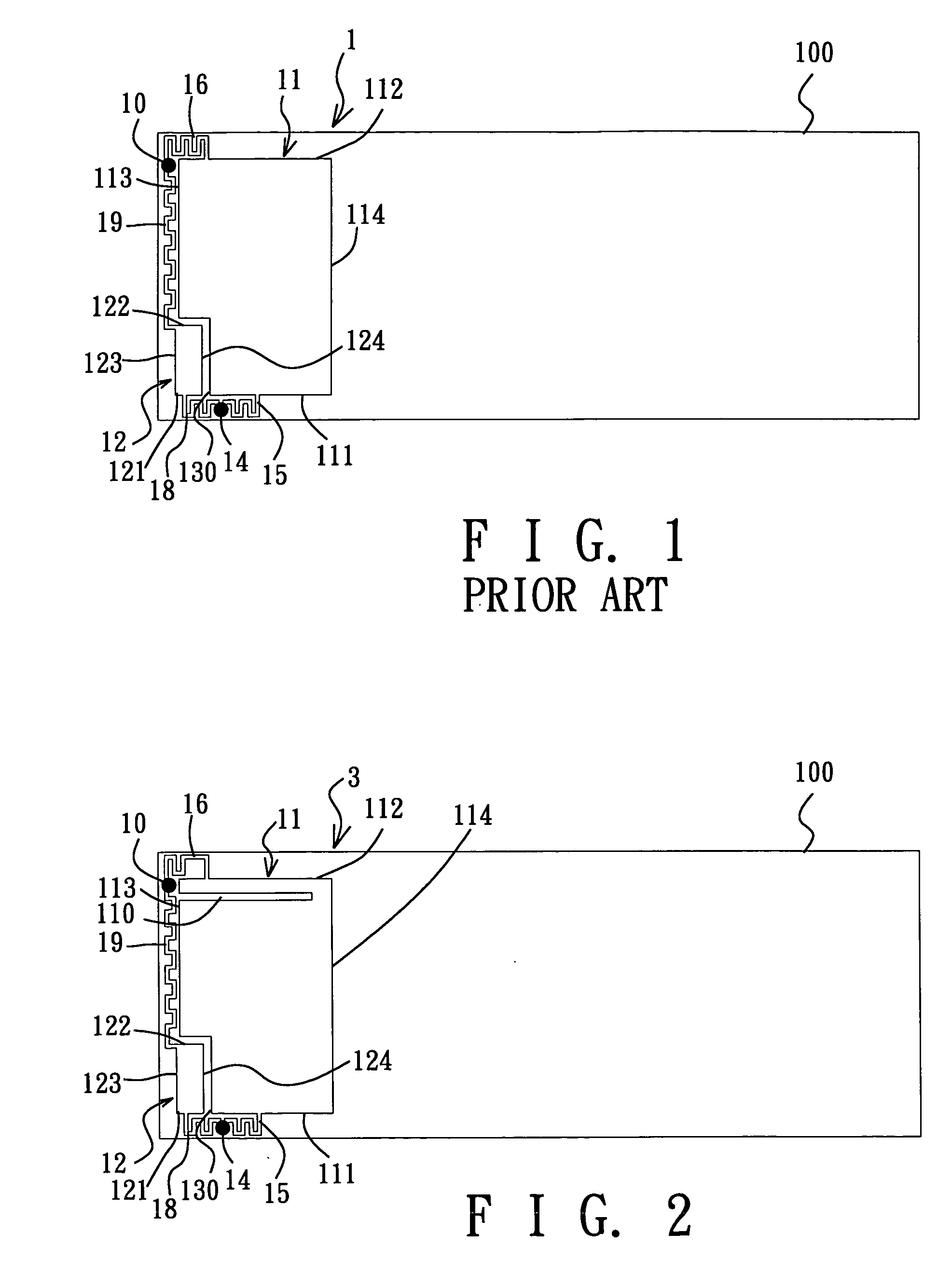
[0016] Referring to FIG. 2, the preferred embodiment of a multi-band planar antenna 3 according to this invention is shown to include first and second radiating elements 11, 12, a feeding point 14, a grounding point 10, first and second feeding strips 15, 18, and first and second grounding strips 16, 19.

[0017] The multi-band planar antenna 3 of this embodiment is to be disposed on a circuit board 100 of a mobile phone (not shown).

[0018] The first radiating element 11 is operable within a first frequency bandwidth, i.e., within the GSM 900 MHz. In this embodiment, the first radiating element 11 is generally rectangular in shape, and has a pair of first and second sides 111, 112 opposite to each other in a first direction, and a pair of third and fourth sides 113, 114 opposite to each in a second direction transverse to the first direction. It is noted that the first and second sides 111, 112 of the first radiating element 11 are shorter than the third and fourth sides 113, 114 of t...


PUM


Abstract

A multi-band planar antenna includes first and second radiating elements. The first radiating element is operable within a first frequency bandwidth. The second radiating element is operable within a second frequency bandwidth. The first radiating element is formed with a slot that generates resonance within the second frequency bandwidth, thereby lowering the VSWR, widening the bandwidth, and increasing the antenna gain of the planar antenna in the second frequency bandwidth.

Description

[0001] CROSS-REFERENCE TO RELATED APPLICATION [0002] This application claims priority of Taiwanese application no. 094122535, filed on Jul. 4, 2005.[0003] BACKGROUND OF THE INVENTION [0004] 1. Field of the Invention [0005] This invention relates to a multi-band planar antenna, more particularly to a multi-band planar antenna applicable to a mobile phone. [0006] 2. Description of the Related Art [0007]FIG. 1 illustrates a conventional multi-band planar antenna 1 disposed on a circuit board 100 of a mobile phone (not shown). The planar antenna 1 includes first and second radiating elements 11, 12, a feeding point 14, a grounding point 10, first and second meandering feeding strips 15, 18, and first and second meandering grounding strips 16, 19. The first radiating element 11 operates within the GSM 900 MHz bandwidth, is rectangular in shape, and has a pair of opposite first and second shorter sides 111, 112, and a pair of opposite third and fourth longer sides 113, 114. The first radi...

Claims


Application Information

Patent Timeline
IPC IPC(8): H01Q1/24H01Q5/357H01Q5/371H01Q5/40
CPCH01Q1/243H01Q1/38H01Q9/0421H01Q5/40H01Q5/357H01Q5/371H01Q21/30
Inventor TSAI, TIAO-HSINGCHIU, CHIEN-PIN
Owner QUANTA COMPUTER INC
Why Eureka
Try Eureka