Method of controlling an electrochromic matrix display and electrochromic display

a technology of matrix display and display, applied in the field of electrochromic matrix display, can solve the problems of inability or inability to connect one separate line to each pixel, matrix display without short-circuit memory will have non-uniform greyscales, and complex manufacturing of active matrix display, etc., to achieve speed up switching, facilitate higher contrast, and uniform contrast

Inactive Publication Date: 2007-01-04
EDWARDS SCI & TECH
View PDF7 Cites 5 Cited by
  • Summary
  • Abstract
  • Description
  • Claims
  • Application Information

AI Technical Summary

Benefits of technology

[0013] The object of the invention is to provide methods for driving electrochromic passive-matrix displays with high and uniform contrast.
[0016] These objects are solved by a principal method for addressing electrochromic matrix displays according to the characterising portion of claim 1. Unlike prior art, the invention uses electric addressing signals on the data lines that are calculated individually for each data line as a function of the distribution of greyscale states of the pixels in the associated column. The select and unselect signals on the select lines are, however, as in prior art, independent of the displayed image. The invention is intended for either preserving a given image or switching between images. In the former case the less restrictive choice of the data line signals facilitates higher contrast than in prior art as well as uniform contrast across the matrix (as in prior art). In the latter case the invention provides means of applying more extreme pixel voltages for short time periods to speed up the switching between different greyscale states for pixels in the display. Finally the invention provides means for preserving and switching images with more than two greyscale states.

Problems solved by technology

When the number of pixels in a display is very large, typically more than 100, it is either physically impossible or impractical to connect one separate line to each pixel.
The pixel circuitry in active-matrix displays improves the addressing properties of the pixels, however, the manufacturing of active-matrix displays is more complicated and expensive.
A known problem (see EP0000616) when SCHEME 1 is applied on electrochromic passive-matrix displays with two greyscale states (light, dark) is related to the greyscale uniformity of the pixels in the matrix.
As a result of this, matrix displays that lack “short-circuit memory” will have non-uniform greyscales.
A drawback of the method is that pixels only are darkened in one of the sub-periods A and B. For a matrix with 7 rows, this means that dark pixels are actively darkened only 1 / 14 of a frame, as compared to 1 / 7 of a frame with SCHEME 1.
One problem with prior art (SCHEME 4) is that the contrast between dark and light pixels is low.
Another problem is that no methods for more than two greyscale states are provided.
Another problem is that no methods for fast image switching are provided.

Method used


Image

  • Method of controlling an electrochromic matrix display and electrochromic display
  • Method of controlling an electrochromic matrix display and electrochromic display
  • Method of controlling an electrochromic matrix display and electrochromic display

Examples


embodiment 1

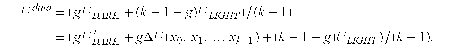
[0019] In embodiment 1 the invented method is used to preserve image patterns in an electrochromic matrix display with only two greyscale states (dark and light). In this embodiment the method is identical to SCHEME 1 in all respects except the choice of electric signals on the data lines. These are, as in SCHEME 1, voltage waveforms with two different voltages UDARK and ULIGHT that are applied on the data lines to selected dark and light pixels, respectively. However, in embodiment 1 UDARK is different for different data lines. UDARK has a monotonic dependence on the number of dark pixels in the column: UDARK(X)=U′DARK+ΔU(X), where U′DARK is a constant, x is the number of dark pixels in the column, and ΔU is a function of x. ΔU is chosen such that the contrast between dark and light pixels becomes uniform across the matrix for arbitrary image patterns. The absolute value of ΔU is increasing with increasing x. The sign of ΔU is such that the absolute value of (UDARK−ULIGHT) always d...

embodiment 2

Time-Division of the Line Addressing Periods

[0026] This embodiment is as embodiment 1 intended for preserving images in an electrochromic matrix display with two greyscale states. It is also based on SCHEME 1 but differs from embodiment 1 in two fundamental ways: Firstly, the same two voltages ULIGHT and UDARK are used on all data lines irrespective of the distribution of dark and light pixels in the columns. Secondly, each line addressing period is divided in two unequally long sub-periods, A and B. The voltages on the data lines Udata are UDARK in A and ULIGHT in B. For selected light pixels the time in A, tA, equals 0 and the time in B, tB, equals tline. For selected dark pixels the time-division between A and B depends on x. tB is equal to tline for a selected dark pixel in a column where only this pixel is dark, i.e., x=1. tB decreases monotonically for increasing x but reaches never zero. In a variant the dependence of tB on x is linear, i.e., tB=tline+(x-1)Δt, where Δt is a ...

embodiment 3

Scheme with Three Select-Line Voltages

[0027] This embodiment is a variant of embodiment 1 for matrix displays with two greyscale states (dark, light). The principal difference is that it is based on SCHEME 2. SCHEME 2 is modified in a similar way as SCHEME 1 is modified for embodiment 1. In the dark frames UDARK is changed into UDARK(x)=U′DARK+ΔUDARK(x) whereas ULIGHT is constant in all columns, ULIGHT=U′LIGHT. In the light frames the situation is reversed: UDARK=U′DARK and ULIGHT(x)=U′LIGHT+ΔULIGHT(x). The values of ΔUDARK(x) and ΔULIGHT(x) are restricted in the same manner as in embodiment 1. Furthermore, as in embodiment 1 preferred variants ΔUDARK(x) and ΔULIGHT(x) are both linearly dependent on x.

[0028] It is also obvious that the time-division of the line-adressing periods in embodiment 2 may be applied also on SCHEME 2 such that a uniform contrast is attained in all columns.


PUM

PropertyMeasurementUnit
voltageaaaaaaaaaa
electrochromicaaaaaaaaaa
greyscaleaaaaaaaaaa

Abstract

Electrochromic matrix and method of controlling the grey state of pixels in an electrochromic matrix display comprising a first set of electrodes being formed of electrically isolated conduction lines, a second set of electrodes being formed of electrically isolated conduction lines, an electrochromic material and an electrolyte being arranged between or on said first and second sets of electrodes and drive means arranged to supply drive voltages selectively to individual electrodes in said first and second sets of electrodes, said first and second sets of electrodes being arranged in a pattern such that each electrode in said first set intersect each electrode in said second set at a single location and such that electrode in said second set intersect each electrode in said first set at a single location, said intersections between the first and of pixels.

Description

TECHNICAL FIELD [0001] The invention relates to electrochromic matrix displays and in particular a method for driving electrochromic passive-matrix displays with uniform colouration of pixels with the same greyscale state. BACKGROUND ART [0002] The basic unit (pixel) of an electrochromic display is an electrochemical cell that may change colour when an electric current goes through the cell. Examples of electrochromic displays are ion-intercalation displays with solid or porous films of e.g. WO3 and TiO2, displays with electrochromic polymer films, metal (e.g. silver) electrodeposition displays, displays with electrochromic action in the electrolyte (containing e.g. viologen molecules), and displays with viologens or other electrochromic agents anchored to the huge inner surface of a porous nanostructured metal-oxide film (e.g. a TiO2 film). These and other types of electrochromic systems are described in more detail in e.g. P. M. S. Monk et al., “Electrochromism: Fundamentals and A...

Claims


Application Information

Patent Timeline
Patent Type & Authority Applications(United States)
IPC IPC(8): G09G3/38G02F1/15
CPCB82Y20/00G09G3/38G02F2202/36G02F1/1523G09G2300/06G09G3/19G09G3/3433
Inventor EDWARDS, MARTEN
Owner EDWARDS SCI & TECH
Why Eureka
Try Eureka