
Sensor elements for supercavitating vehicles

Inactive Publication Date: 2007-01-04
THE JOHN HOPKINS UNIV SCHOOL OF MEDICINE
View PDF3 Cites 2 Cited by
  • Summary
  • Abstract
  • Description
  • Claims
  • Application Information

AI Technical Summary

Benefits of technology

[0007] The present invention pertains to sensing elements that quickly and accurately determine if a first changing media of a first index of refraction or a second changing media of a second index of refraction is present around the sensing elements. These sensing elements find particular application in identifying the location of the cavity wall in which a supercavitating vehicle is operating, relative to the vehicle, particularly where the first media is a liquid and the second media is a gas. In certain embodiments signal emitting elements carried on the vehicle emit signals towards the presumed position of the cavity wall, and sensing elements carried on the vehicle receive the emitted signals after they are reflected off of the cavity wall. The sensing elements identify the location where the reflected signal is received, and based on this identified location, the location of the cavity wall is determined. In alternative embodiments, sensing elements are positioned along fins extending outward with respect to the hull of the vehicle, and the sensors sense the presence of liquid or gas. Sensors sensing gas identify portions of the fin that are located within the cavity, and sensors sensing liquid identify portions that are located beyond the cavity wall. This enables quick and accurate location of the location of the cavity wall.

Problems solved by technology

The non-linear and high-speed nature of supercavitation makes control of supercavitating projectiles and vessels difficult.
As is well known, a supercavitating vehicle operates within a cavity formed around the vehicle and contact between the supercavitational vehicle and the wall of the cavity increases the friction and thus the drag exerted on the vehicle.

Method used


Image

  • Sensor elements for supercavitating vehicles
  • Sensor elements for supercavitating vehicles
  • Sensor elements for supercavitating vehicles

Examples


Embodiment Construction

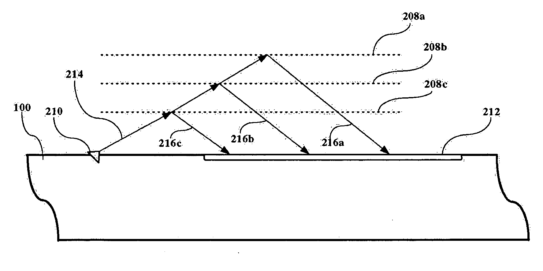
[0015] The present invention is a method and system for sensing the presence of changing media having differing indices of refraction, e.g., gas or liquid, around a sensor, and in a preferred embodiment, this information is used for monitoring the location of the cavity wall surrounding a supercavitational vehicle, relative to that vehicle. The examples illustrated herein all pertain to underwater vessels where the vessel is operating in water and the cavity is formed by the absence of water created by a cavitation. However, it is understood that the sensors of the present invention can be used in any environment where the sensor is in contact with media having differing indices of refraction; air and water are used for the purpose of example. It is contemplated that a shock boundary between two gaseous media (as would be found in a supercavitating missile operating in the earth's atmosphere) could be detected using the principles of the present invention.

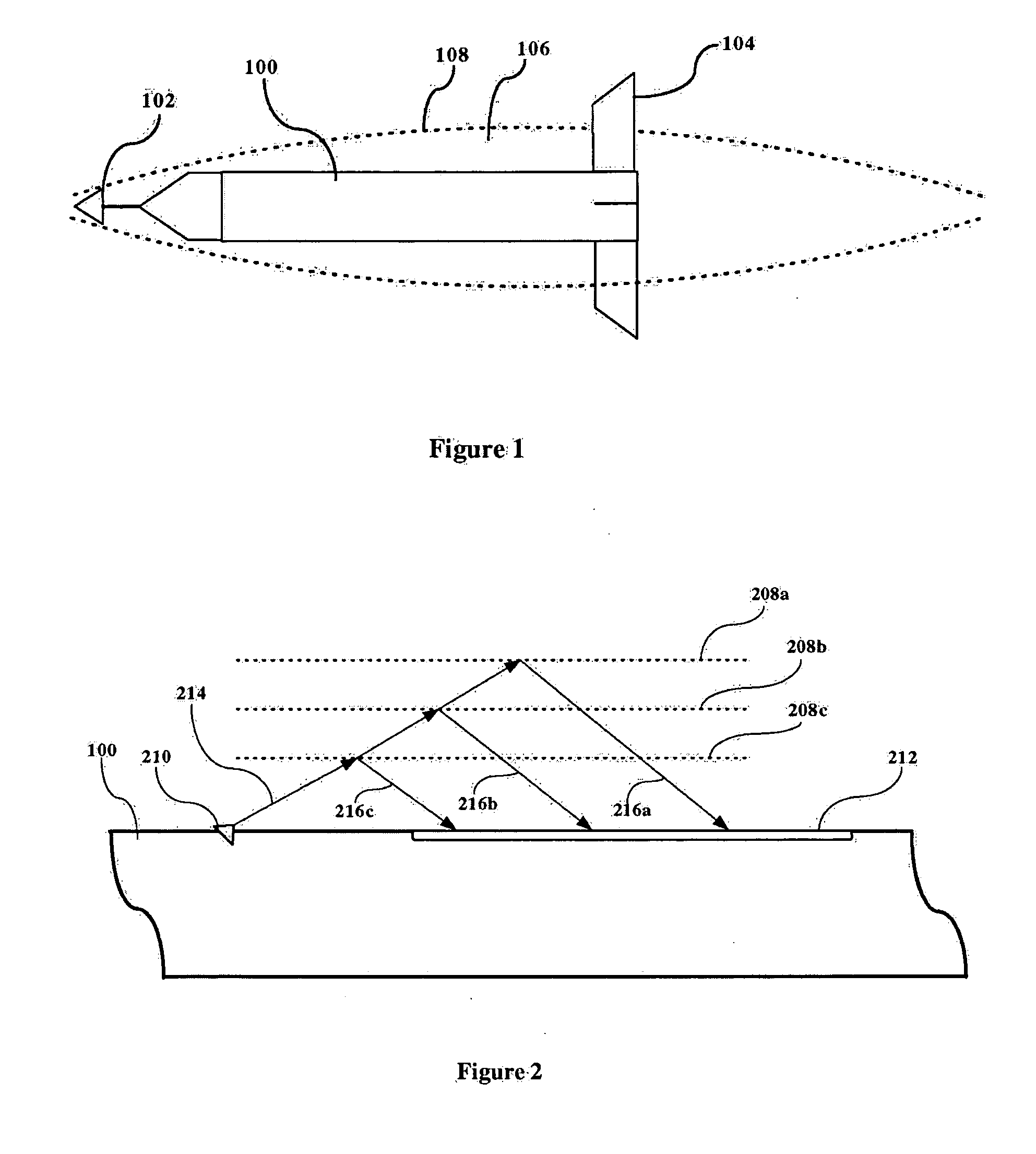
[0016]FIG. 1 illustrates t...


PUM


Abstract

Sensing elements that quickly and accurately determine if a liquid or gas is present around the sensing elements are disclosed. These sensing elements find particular application in identifying the location of the cavity wall in which a supercavitating vehicle is operating, relative to the vehicle. In certain embodiments signal emitting elements carried on the vehicle emit signals towards the presumed position of the cavity wall, and sensing elements carried on the vehicle receive the emitted signals after they are reflected off of the cavity wall. The sensing elements identify the location where the reflected signal is received, and based on this identified location, the location of the cavity wall is determined. In alternative embodiments, sensing elements are positioned along fins extending outward with respect to the hull of the vehicle, and the sensors sense the presence of liquid or gas.

Description

CROSS-REFERENCE TO RELATED APPLICATIONS [0001] This application claims the benefit of prior filed co-pending U.S. application Ser. No. 60 / 695,337, filed on Jun. 30, 2005, the content of which is incorporated fully herein by reference.BACKGROUND OF THE INVENTION [0002] 1. Field of the Invention [0003] This invention relates to methods and systems for sensing the presence or absence of liquid or gas around a sensor and, more particularly, for sensing and tracking the location of the wall of the cavity formed about a supercavitating vehicle and, even more particularly, to the sensing and identifying the location of the cavity wall relative to an underwater supercavitating vehicle without measuring the time-of-flight of an optical or RF signal. [0004] 2. Description of the Related Art [0005] The U.S. Navy has funded long-running research programs for controlling supercavitating projectiles and vessels, referred to herein generically as supercavitating vehicles. Some of this work extends...

Claims


Application Information

Patent Timeline
IPC IPC(8): G02B5/10
CPCB63B17/00G01N21/552G01N21/55B63J99/00
Inventor FOWLER, KIM R.GAUTHIER, LEO R. JR.
Owner THE JOHN HOPKINS UNIV SCHOOL OF MEDICINE
Learn More