
Backlight unit

Inactive Publication Date: 2007-01-04
LG DISPLAY CO LTD
View PDF15 Cites 3 Cited by
  • Summary
  • Abstract
  • Description
  • Claims
  • Application Information

AI Technical Summary

Benefits of technology

[0028] An advantage of the present invention is to provide a backlight unit that converts ultraviolet light emitted from light-emitting lamps into visible light and reflects the visible light, thus achieving improved luminance.

Problems solved by technology

However, CRTs do not have a small size and are not lightweight.
However, CRTs have a large size and are heavy in weight.
Currently, there is a desire for small and light electronic products, but it is difficult to reduce the weight and size of CRTs.
As a result, lamps in direct-type backlight units frequently malfunction and have a short life span compared to the lamps in edge-type backlight units.
The possibility that lamps are not properly turned on or off is larger in direct-type LCD devices than in edge-type LCD devices.
As a result, the ultraviolet light emitted from the light-emitting lamps cannot be utilized without the reflection sheet.
The reflection sheet of the related art direct-type backlight unit is configured to absorb ultraviolet light emitted from the light-emitting lamps, making it impossible to effectively utilize light emitted from the light-emitting lamps.
Accordingly, improving the luminance of the backlight unit is limited.
Therefore, improving the luminance of related art direct-type backlight units is limited.

Method used


Image

  • Backlight unit
  • Backlight unit
  • Backlight unit

Examples


Embodiment Construction

[0038] Reference will now be made in detail to exemplary embodiments of the present invention, examples of which are illustrated in the accompanying drawings. Wherever possible, the same reference numbers will be used throughout the drawings to refer to the same or similar parts.

[0039] A backlight unit according to an embodiment of the present invention will be described with reference to FIGS. 3 and 4.

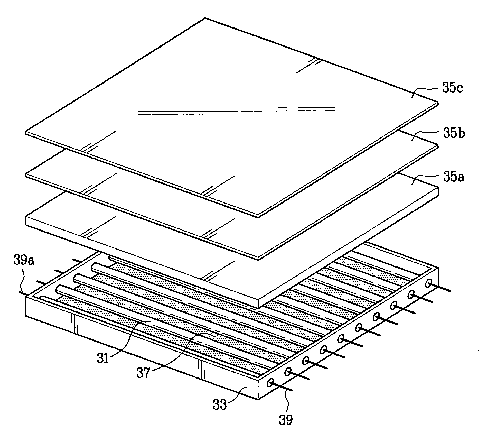
[0040]FIG. 3 is a schematic view showing a backlight unit according to an embodiment of the present invention and FIG. 4 is a perspective view showing a reflection sheet used in the backlight unit of FIG. 3.

[0041] As shown in FIG. 3, the backlight unit for a liquid crystal display (LCD) device according to an embodiment of the present invention includes a plurality of light-emitting lamps 31 arranged substantially in parallel, an outer case 33 that fixes and supports the light-emitting lamps 31, and light scattering means 35a, 35b and 35c arranged between the light-emitting lamps 3...


PUM


Abstract

A backlight unit that converts ultraviolet light emitted from light-emitting lamps into visible light is disclosed. The backlight unit also reflects the visible light, thus achieving improved luminance. The backlight unit includes a plurality of light-emitting lamps arranged substantially in parallel, an outer case that fixes and supports the light-emitting lamps, and a reflection sheet disposed within the outer case and containing a fluorescent material that converts ultraviolet light into visible light and reflects the visible light.

Description

[0001] This application claims the benefit of Korean Patent Application No. 10-2005-0058419, filed on Jun. 30, 2005, which is hereby incorporated by reference for all purposes as if fully set forth herein. BACKGROUND OF THE INVENTION [0002] 1. Field of the Invention [0003] The present invention relates to a backlight unit, and more particularly, to a backlight unit including a reflection sheet that contains a fluorescent material sensitive to ultraviolet light. [0004] 2. Discussion of the Related Art [0005] Many display devices have been developed and used. Of these devices, cathode ray tubes (CRTs) are mainly used in monitors of television (TV) sets, measuring instruments, information terminals, etc. However, CRTs do not have a small size and are not lightweight. A small size and a light weight are beneficial in electronic products. However, CRTs have a large size and are heavy in weight. [0006] Currently, there is a desire for small and light electronic products, but it is difficu...

Claims


Application Information

Patent Timeline
IPC IPC(8): F21V7/04
CPCG02B6/0055G02F1/133605G02F1/133604G02F1/1335
Inventor CHO, JUNG ILL
Owner LG DISPLAY CO LTD
Features
  • Generate Ideas
  • Intellectual Property
  • Life Sciences
  • Materials
  • Tech Scout
  • Unparalleled Data Quality
  • Higher Quality Content
  • 60% Fewer Hallucinations
Learn More