Cooperative relay transmission method for wireless communication system

a wireless communication system and relay technology, applied in the field of cooperative relay transmission method of wireless communication system, can solve the problem of limitation of transmit diversity technique using multiple antennas in uplink transmission

Inactive Publication Date: 2007-01-04
SAMSUNG ELECTRONICS CO LTD
View PDF2 Cites 160 Cited by
  • Summary
  • Abstract
  • Description
  • Claims
  • Application Information

AI Technical Summary

Benefits of technology

[0006] Accordingly, the present invention has been designed to solve the above and other problems occurring in the prior art. Therefore, it is an object of the present invention to provide a cooperative relay transmis...

Problems solved by technology

However, there are limitations in applying the transmit diversity technique using multiple antennas ...

Method used


Image

  • Cooperative relay transmission method for wireless communication system
  • Cooperative relay transmission method for wireless communication system
  • Cooperative relay transmission method for wireless communication system

Examples


first embodiment

[0034]FIG. 3 is a flowchart illustrating the cooperative relay transmission method in accordance with the present invention.

[0035] As illustrated in FIG. 3, a base station initializes parameters for relay communication (Step S301). The parameters for relay communication include the maximum number of relay terminals, Nmax, the minimum number of relay terminals, Nmin, and a required relay channel quality Q and an allowable relay distance D corresponding to parameters for setting a relay function of a terminal. When the initialization is completed, the base station sends the relay channel quality Q and the allowable relay distance D to linked terminals (Step S302).

[0036] Upon receiving Q and D, each terminal measures a channel state Qpresentand a distance Dpresent associated with the base station and then compares Qpresent and Dpresent with Q and D. When either one or both of the two conditions are satisfied, the terminal activates its relay function and becomes a possible relay termi...

second embodiment

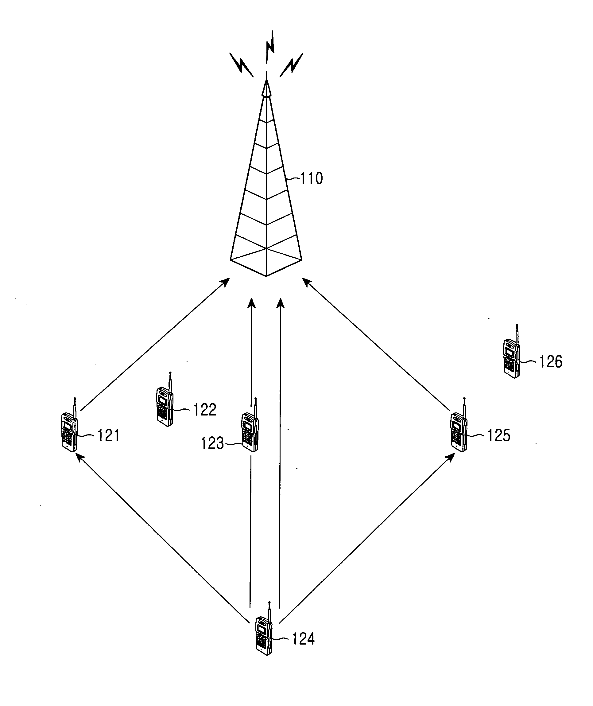
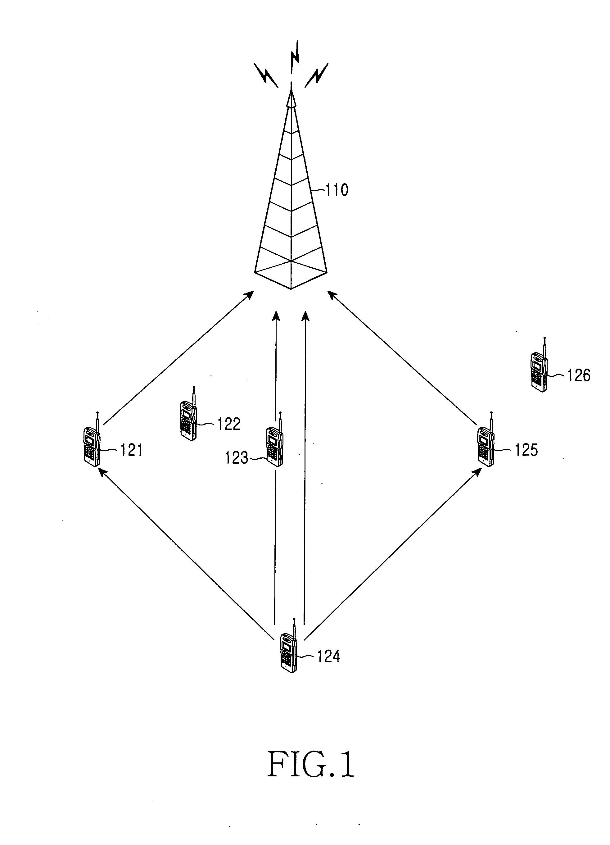
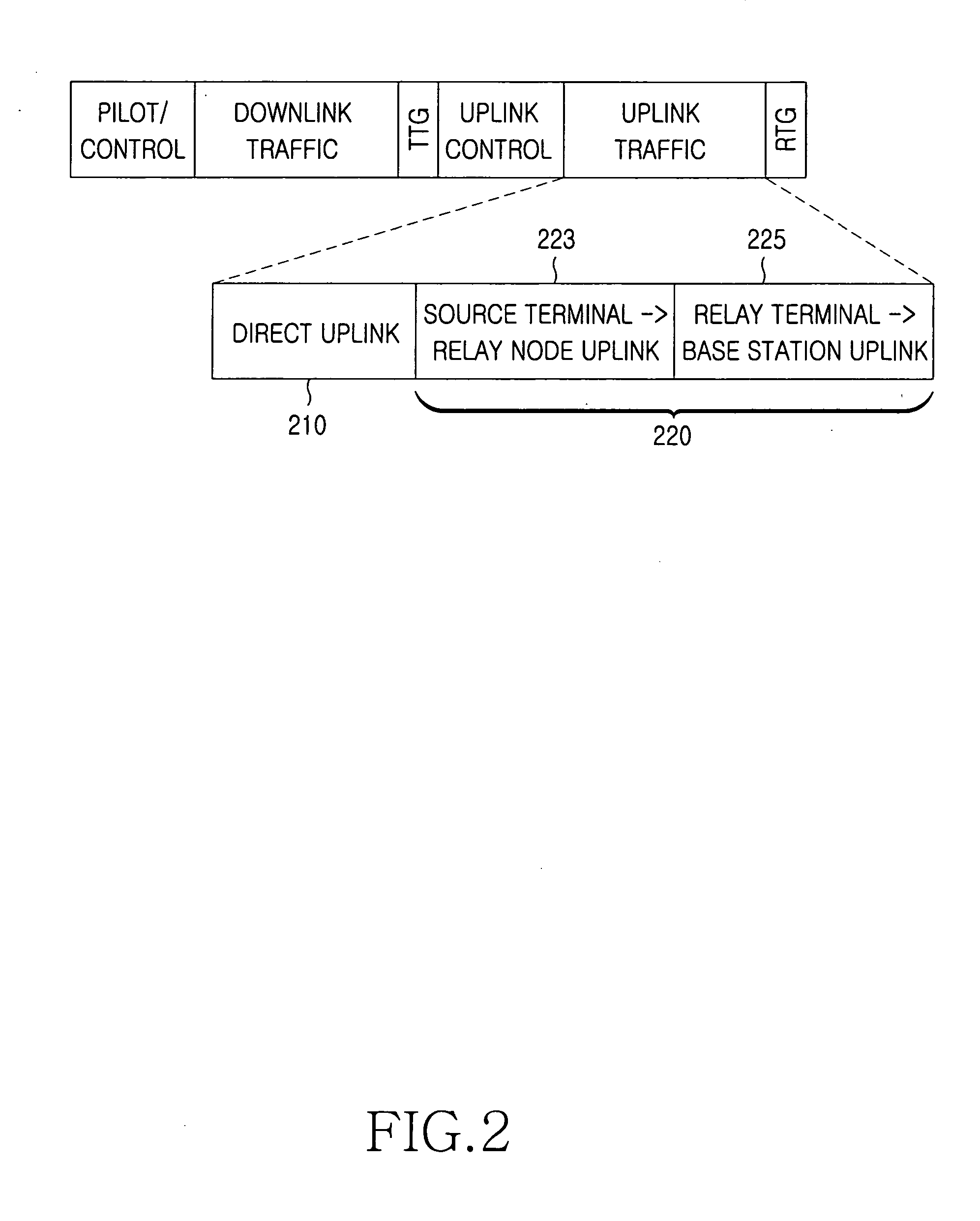
[0040] On the other hand, when a possible relay terminal receives an uplink signal from the source terminal in the cooperative relay transmission method in accordance with the second embodiment, it decodes the received signal. If the decoding operation is successful, the possible relay terminal becomes a relay terminal and temporarily stores the uplink signal. Upon receiving a re-transmission request message from the base station, the relay terminal transmits the temporarily stored uplink signal to the base station.

[0041] In response to the re-transmission request message, the base station receives uplink signals from the relay terminals (Step S343), combines the received uplink signals (Step S344), and decodes the combined signals (Step S345).

[0042] In this embodiment, all relay terminals transmit an uplink signal upon receiving a retransmission request message and successfully performing a decoding operation, respectively. Alternatively, one terminal can transmit an uplink signal...


PUM


Abstract

Disclosed is a method in a base station for providing a network access service to terminals. Where one of the terminals is selected as a source terminal and at least one of the other terminals is used as a relay node for relaying communication between the base station and the source terminal. Parameters for relay communication are initialized. A relay communication request message including that the parameters is transmitted. In response to the message, a terminal independently sets and performs the relay communication between the base station and the source terminal. Uplink signals are received from the source and relay terminals. The uplink signals received from the source and relay terminals are combined and decoded. A transmit diversity gain is obtained in uplink transmission of a terminal with a single antenna because relay nodes retransmit the source terminal's signal.

Description

PRIORITY [0001] This application claims priority under 35 U.S.C. § 119 to an application entitled “Cooperative Relay Transmission Method for a Wireless Communication System” filed in the Korean Intellectual Property Office on Jul. 4, 2005 and assigned Serial No. 2005-59900, the contents of which are incorporated herein by reference. BACKGROUND OF THE INVENTION [0002] 1. Field of the Invention [0003] The present invention relates generally to a wireless communication system, and in particularly, to a cooperative relay transmission method for a wireless communication system that can obtain a diversity gain by sharing transmission from a transmitter to a receiver with adjacent relay terminals. [0004] 2. Description of the Related Art [0005] Generally, transmit diversity is implemented through data transmission using multiple transmit antennas. A typical example is a Multiple-Input Multiple-Output (MIMO) system. The MIMO system is combined with a space-time coding scheme and is being es...

Claims


Application Information

Patent Timeline
IPC IPC(8): H04L12/28H04Q7/00H04J3/08H04Q7/24H04J3/04H04W48/10H04W88/04
CPCH04B7/022H04B7/026H04W88/04H04W48/10H04B7/15592
Inventor PARK, SEUNG-YOUNGPARK, DAE-YOUNGYUN, SANG-BOH
Owner SAMSUNG ELECTRONICS CO LTD
Why Eureka
Try Eureka