Image generation device, image generation method, and image generation program

a technology of image generation and image acquisition, applied in the direction of road vehicle traffic control, traffic control system, instruments, etc., can solve the problems of difficult to understand the relationship between image acquisition and convenience improvemen

Inactive Publication Date: 2007-01-04
OLYMPUS CORP
View PDF10 Cites 64 Cited by
  • Summary
  • Abstract
  • Description
  • Claims
  • Application Information

AI Technical Summary

Benefits of technology

[0076] Thereby, the display device ...

Problems solved by technology

However, the conventional monitor camera device such as the above has a problem that it is difficult to understand the relationship between an image acquisition means arrangement object such as a vehicle on which the camera is mounted and a monitored tar...

Method used


Image

  • Image generation device, image generation method, and image generation program
  • Image generation device, image generation method, and image generation program
  • Image generation device, image generation method, and image generation program

Examples


first embodiment

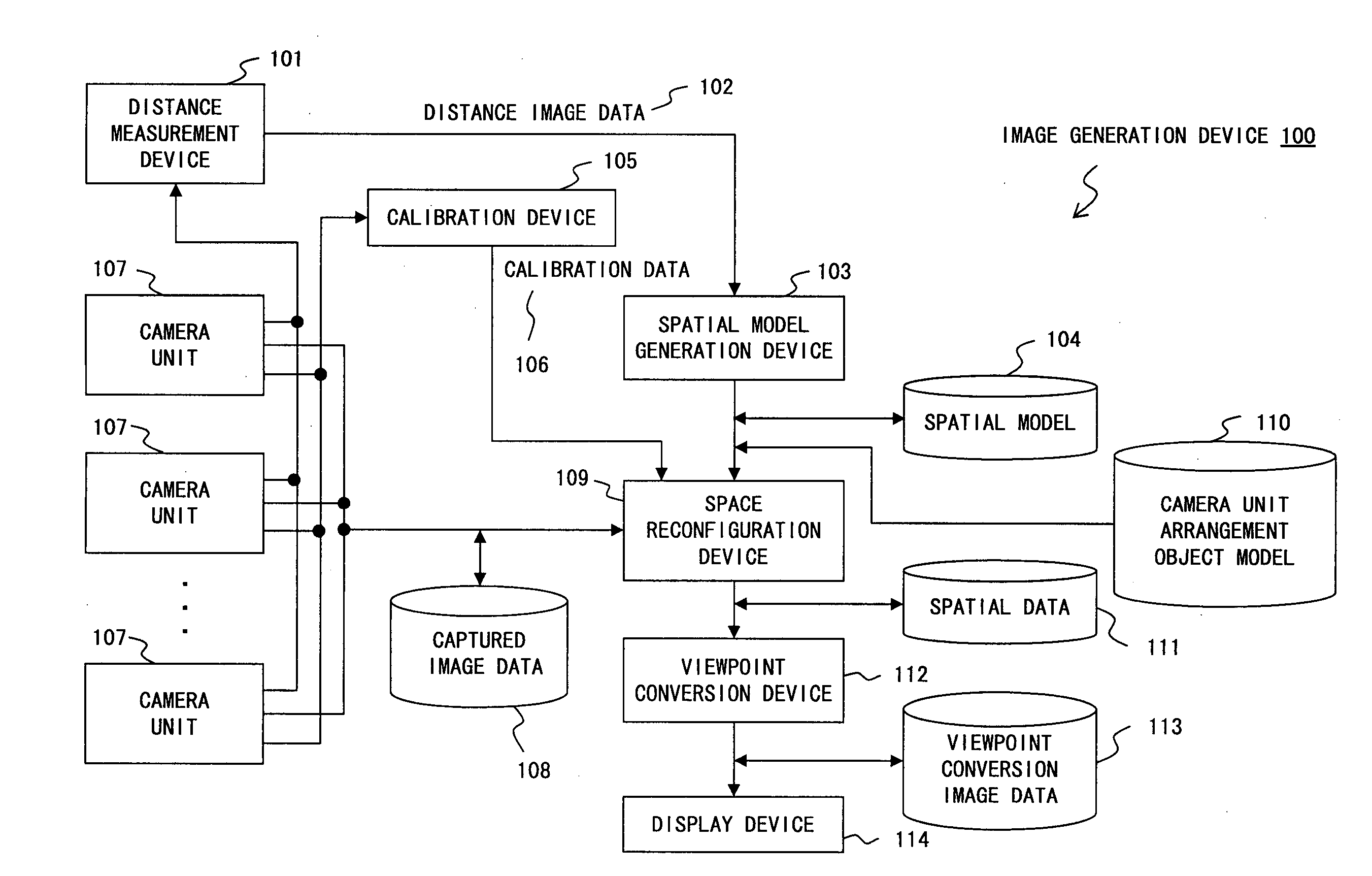
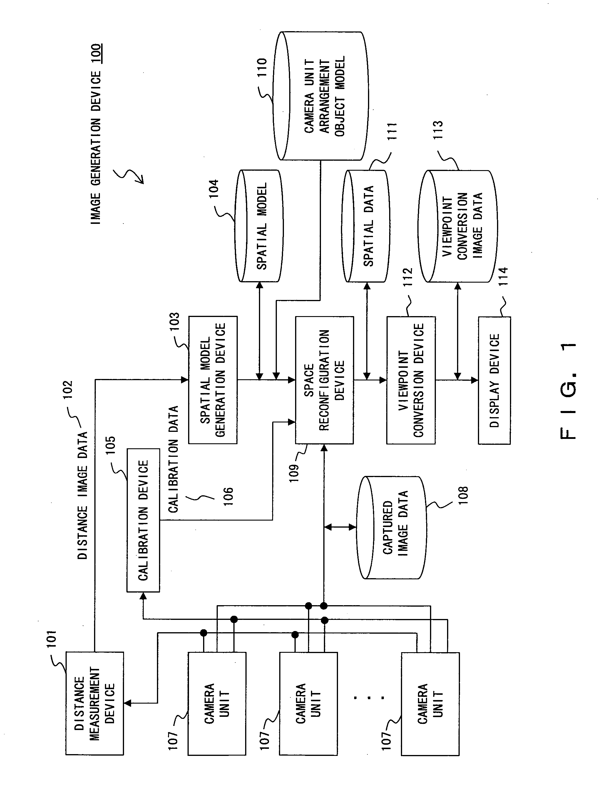
[0122] First, an image generation device for generating an image viewed from a virtual viewpoint based on image data acquired by a plurality of cameras, and for displaying the image viewed from the virtual viewpoint will be explained by referring to FIG. 1 and FIG. 2. Additionally, a plurality of cameras are used in the examples of these figures, however, it is possible to acquire, by sequentially changing the arrangement position of one camera, image acquisition data that is equivalent to that acquired in the case where a plurality of cameras are provided. The above one or a plurality of cameras is arranged in an image acquisition means arrangement object such as a vehicle, a room (a particular zone of the room or the like), a building or the like. This point is applied to the examples explained below.

[0123]FIG. 1 is a block diagram of the image generation device for generating a spatial model by a distance measurement device, and for generating a viewpoint conversion image.

[0124...

second embodiment

[0225]FIG. 18 explains a second embodiment in which the present invention is applied to indoor monitoring cameras.

[0226]FIG. 18 shows a room as a monitored target as viewed from above (i.e. the ceiling). Four stereo camera units 107A, 107B, 107C and 107D, which are monitoring cameras, are arranged in arbitrary places in the room for acquiring images in the room.

[0227] For example, the stereo camera units 107A, 107B, 107C and 107D may be arranged at the four corners of the center of the ceiling of the room, alternatively, it is also possible that ultra wide angle cameras in the vicinity of the ceiling. Further, these stereo camera units 107A, 107B, 107C and 107D can be stereo cameras each having a combination of binocular, trinocular or further configuration. Naturally, in place of these stereo cameras, the measurement devices 101 and 201 (for example, a laser radar, a slit scan measurement device, an ultra radio wave sensor, a model of a room made by the CAD) can be used together....

third embodiment

[0241] In a third embodiment of the present invention, a blind spot for a driver is detected and a viewpoint is set for observing the detected blind spot in order that the driver can see the virtual viewpoint image viewed from such a viewpoint. Alternatively, from the above detected blind spot, the blind spot which has to be displayed is selected based on driving operation information, operations by the driver or the like, the viewpoint for observing the selected blind spot is set, and the virtual viewpoint image viewed from the set viewpoint is displayed for the driver. Hereinbelow, the third embodiment of the present invention will be explained sequentially and specifically by referring to the drawings.

[0242]FIG. 19 shows an image generation device 10000 according to the third embodiment of the present invention.

[0243] In FIG. 19, the image generation device 10000 comprises one or a plurality of cameras 2101, a camera parameter table 2103, a space reconfiguration unit 2104, a sp...


PUM


Abstract

The image generation device includes distance calculation means for calculating a distance between a space model and an imaging device arrangement object model which is a model such as a vehicle having a camera mounted, according to viewpoint conversion image data generated by viewpoint conversion means, captured image data representing captured image, a space model, or mapped space data. When displaying an image viewed from an arbitrary virtual viewpoint in the 3D space, the image display format is changed according to the distance calculated by the distance calculation means. When displaying a monitoring object such as a vicinity of a vehicle, a shop, a house or a city as an image viewed from an arbitrary virtual viewpoint in the 3D space, it is possible to display the monitoring object in such a manner that the relationship between the vehicle and the image of the monitoring object can be understood intuitionally.

Description

CROSS REFERENCE TO RELATED APPLICATIONS [0001] This is a Continuation Application of PCT Application No. PCT / JP2005 / 002976, filed Feb. 24, 2005, which was not published under PCT Article 21(2) in English.[0002] This application is based upon and claims the benefit of priority from the prior Japanese Patent Application Nos. 2004-069237 and 2004-075951, filed on Mar. 11, 2004 and Mar. 17, 2004, the entire contents of which are incorporated herein by reference. BACKGROUND OF THE INVENTION [0003] 1. Field of the Invention [0004] The present invention relates to an image generation device, an image generation method and an image generation program for producing image data for displaying an image in such a manner that a relationship between an object and captured images can be understood intuitively when an image obtained by synthesizing, a plurality of images acquired by one or a plurality of cameras mounted on the above object such as a vehicle or the like, based on image data correspon...

Claims


Application Information

Patent Timeline
IPC IPC(8): G06K9/36G06T1/00G06T15/20G08G1/16H04N7/18
CPCG08G1/16G06T15/20G08G1/167
Inventor MIYOSHI, TAKASHIIWAKI, HIDEKAZUKOSAKA, AKIO
Owner OLYMPUS CORP
Why Eureka
Try Eureka